


To use the computer controlled cutting devices, first we need to create a digital model of the design we want to use for cutting.
Vinyl cutter
I took my design inspiration for the vinyl cutting task from the pattern which exists on the internal surface of the dome in a historical building which is located in Isfahan-

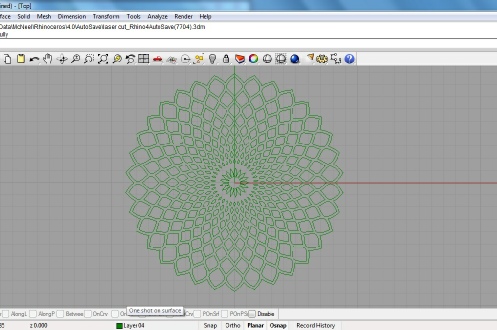
As it can be seen, the pattern consists of curves in different shapes and sizes. In order to draw them I needed to work with a software which would allow me to draw these curves using its strong tools. Rhino, the software I recently started to work with seems to offer adequate qualities for this purpose.
Next step would be to transfer this drawing to a format which is recognized by the cutter machine. Despite the fact that we could transfer other drawings to the machine using the ‘fab module’ yet as we tried we couldn’t transfer this shape. Instead we used the ‘serif draw plus’ which made a smooth conversion of the DXF format to the machining tool path.
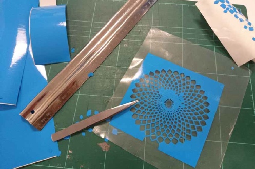
The machine cut the vinyl accurately. It actually has exceeded my expectations. When I was drawing the pattern the outcome was not very clear since the smallest shapes were drawn as small as 1 mm wide. But apparently the machine is capable of cutting shapes even smaller than that.
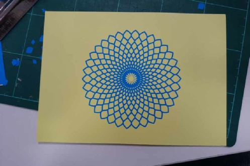
After applying a layer of tape over the vinyl and removing the unneeded parts and sticking it on the card the final product is ready.
Laser cutter
Using a laser cutter and acrylic sheets to make press-
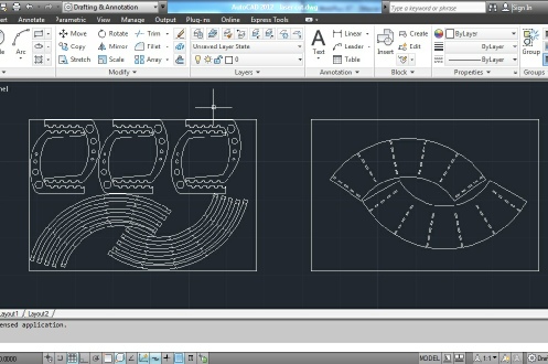
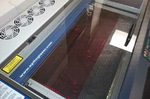
Although I did not make the lines as ‘polyline’ yet the cutter somehow cut the lines indiscriminately just like if each box is drawn as polylines. During the cutting process some lines were not cut or half cut randomly. It is strange because there was not any problem on other identical components. To solve this problem, after the cutting job on the work piece was done, I had to not touch the work piece and remove all the other lines in the drawing and keep only the troubled lines and redo the cutting; therefore the problem was solved. When I wanted to cut the second sheet I forgot to turn on the machine’s fan. In just a few seconds there was a lot of smoke inside the device and strong smell came out of it. Fortunately I managed to pause the machine and start the fans and resume the process. After the cutting was finished I notices that fortunately there was no problem with part despite the pause during the cutting.
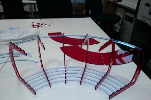
Finally the parts were ready for assembly. When I started to assemble them realized that I cut the components with zero tolerance. Such a design would work in a perfect world but laser cutter may deform the materials such as acrylic with the produced heat. The material sheets did not have 100% consistency in their thickness. In addition this material is also very fragile and not flexible, thus joining needed some work yet because the component design had been done precisely, parts came together eventually.
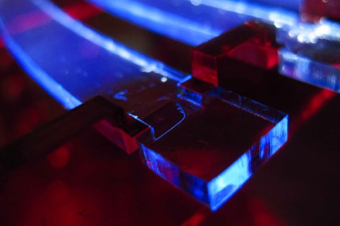
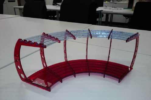
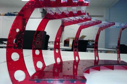
In the end all of the parts are assembled. The joints are perfect. It seems that the combination of precise design and computer controlled cutting devices can produce outstanding artefacts.
By clicking on this link and this link you can access the CAD files.
