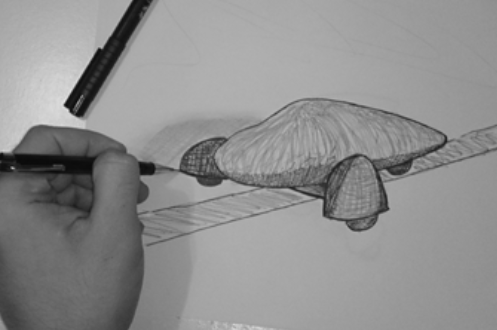


By looking at the project concept it can be seen that the car shaped body of the robot has a quite complex geometry comprised of numerous curves in any directions of the surface. In order to model a highly complicated geometry, nowadays using strong modelling applications seems to be a must. As an Architect, I started using the 2D and then 3D ‘AutoCAD’ from the early years of my studies. Its convenience, speed and precision have made it very useful at that stage. Nevertheless when faced more complicated geometries ‘3DS MAX’ become handy due to its fabulous settings which would allow me to manipulate the design models in many ways in order to get the desired results. Its powerful rendering engine also provides a well established platform for visualization and project presentation.
Nonetheless for this project I intend to use the ‘Rhino’ modelling application. Apart from all the above mentioned advantages, Rhino also provides a good link to digital fabrication as well as parametric features which pave the way for a computer-
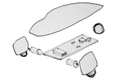
To move further from the concepts and realize every components of the design it is essential to know the constraints and the relationships of each component with others. In this case it can be seen that there are electronic boards, mechanical components, chassis and the body forming the whole product. At the moment I am not aware of the properties of electronics and mechanical parts, therefore, the modelling of the body is based on hypothetic constraints and dimensions for now and the development of the body design will happen based on the knowledge which will be gathered later.
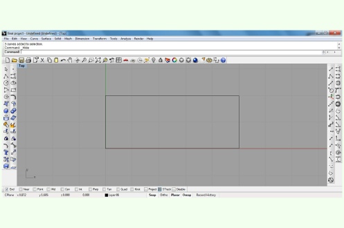
For starter it can be helpful to use a general standard car size (5m*2m) as a dimensional guide. Some straight lines could be used to guide the drawing of the curved body.
Guide lines could be drawn in two or three dimensional spaces to facilitate the form generation process.
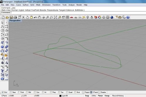
Curves are drawn with the help of the guide lines. They can be then adjusted to reach to a desired form.
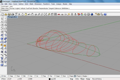
Ribs are added to the key points where curves and the surface have significant changes. Ribs also may be adjusted to provide desired base for the final surface.
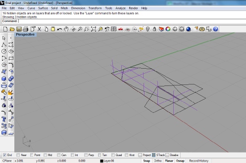
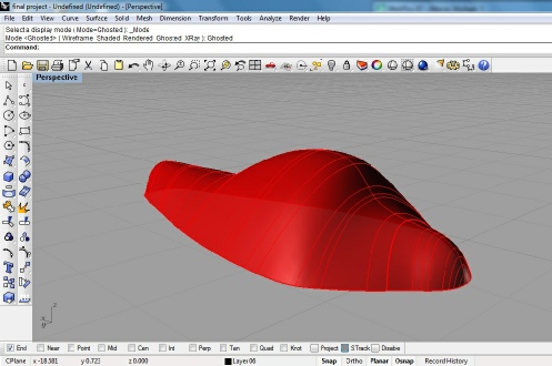
Based on designed curves and ribs a surface can be produced. The surface itself can be manipulated using a large variety of modification tools.
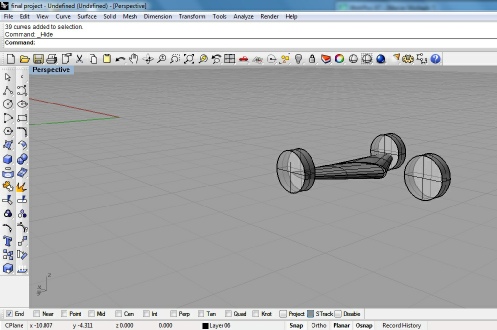
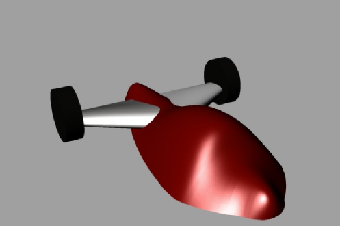
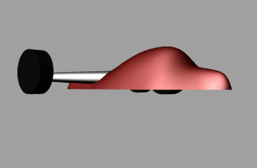
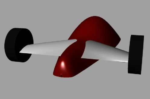
Wheels and wings are modelled using the same technique and are placed in their location under the body.
By adding materials and suitable light we can have a model, prepared for rendering. It can be seen that the concept is already developing. Based on the fact that in this kind of robots having the moving wheels in the rear part of the robot provides better traction and steering, opposing the concept proposal, in the digital model moving wheels are placed in the back.
By clicking this link you access the rhino file.