

As I have mentioned in my First week’s assignment (Final project concept) my product for the final project of the fablab course is going to be a line following robot. I can say that when I started this course I was competent in modelling and form generation using CAD applications but had close to zero knowledge of electronics and programming. Therefore I decided to make this project more challenging for myself by choosing a project which contains more of electronics and programming. I also did not want to make it so complicated that it would be impossible for me to finish the project with the knowledge I could be able to gain in this limited time. The other reason why I chose this project is that when I reviewed the weekly assignments, there was different topics for each week and I wanted to use as many as possible of those skills we gain throughout the course. With a quick review I realized that a line following robot contains input devices, possibly a network of boards, output devices, mechanics, programming, electronics design, electronics production, CAD, CAM and many other skills. Such a project can combine all the skills we learn at the ‘fab lab’.
Initial Planning
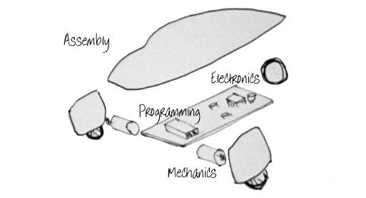
While different parts and pieces of a project should be gathered and work together in a harmony, is it always good to break it down into different fields of work to actually realize what jobs need to be done. I have divided the project activities into five main groups; electronic design and production, programming, mechanics, CAD and assembly. In my opinion the main field in this group is the electronics due to the fact that most of the development in other groups are highly related to the working condition of the electronic parts and their dimensions. Thus the first priority is to design and produce the electronics.
Electronics
In order to know how this type of machines work I needed to do some research. I started my research by reading some parts of the ‘robot building for beginners’ and the ‘intermediate robot building’ both written by ‘David Cook’. I realized that a line follower basically has light sensors which sense the difference between the light back ground and dark line. These input components then send the signals to the Micro controller. Based on the program, micro controller sends power to the two dc motors which can steer the robot to the left or right.
Based on the general concept I am going to order the components I need. The main components were specified through research and reading components’ data sheets but the completed list of components was finalized through time. Basically whenever I realized a function needed to be added to the robot I searched for the necessary components and added them to the design.
Below is the list of the main components that I used in producing my robot. Thay could be acquired from the ‘RS components’.
Role
Micro controller
Voltage comparator
Motor driver
Potentiometer
IR reflector Pair
Model
PIC18F4550
LM393N
L293D
10K
TCRT5000
£ 4.5
£ 0.40
£ 3.0
£ 2.0
£ 0.7
Each
“
“
“
5-
Price
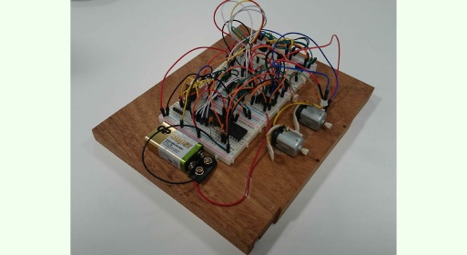
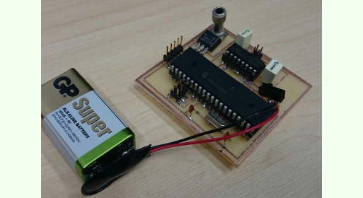
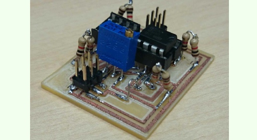
For a beginner like me it is the best to experience the electronics by playing with the components, it is also important to refer to the data sheets for the essential info. On the other hand I could not directly start designing my boards with a CAD application. Therefore I started to assemble my components on a breadboard and because of that I needed to use through hole components. First I checked the prototype by a multi meter, but the final tests and adjustments (such as in the potentiometers) happened after programming the micro controller which will be discussed later. Below shows a picture of my electronics prototype. (Four weeks for a beginner like me!)
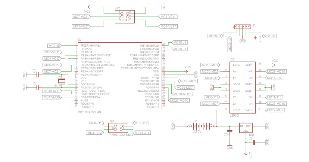
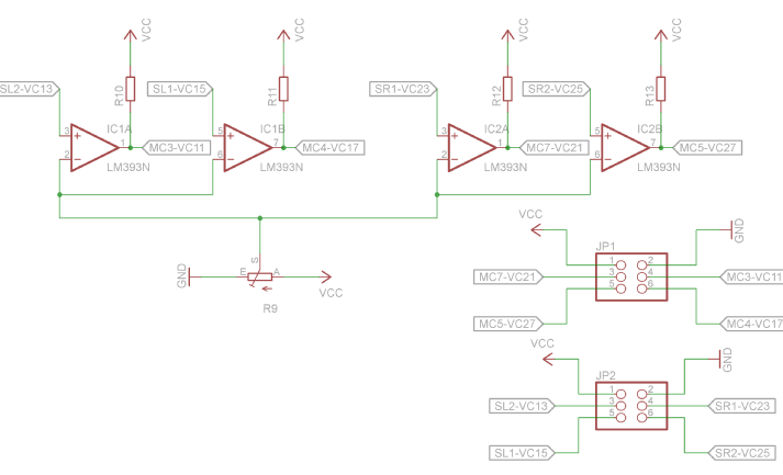
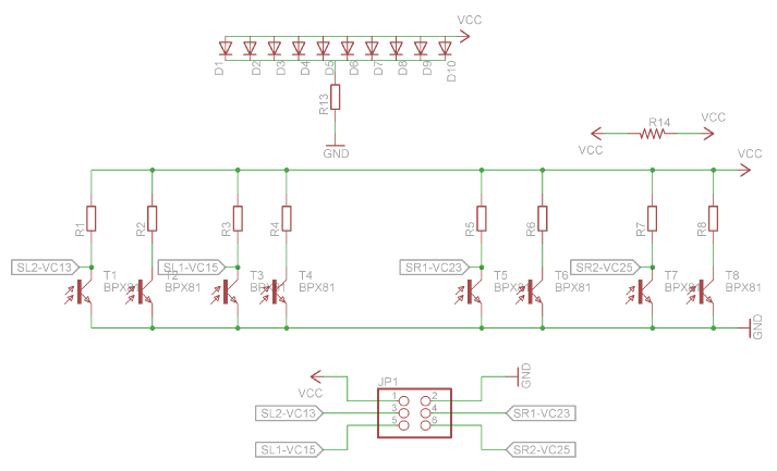
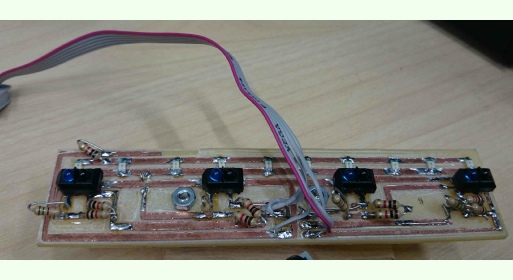
After developing the project on breadboard, it is time to design and make the PCB boards. I used eagle to design the boards and the ‘Modela’ to cut them. Based on the nature of my device and limits of Modela I needed to divide the components in three different boards. First one containing the micro controller and the motor driver, which are connected to the main power (9V battery). Second one contains two voltage comparator that process the voltage sent from sensors and a potentiometer. The third board consists of four IR reflector pairs and some LED headlights. The first, second and third boards are connected together respectively. (Schematic and PCB design took one week)


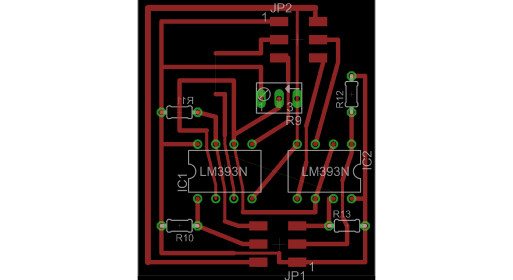
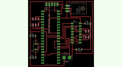
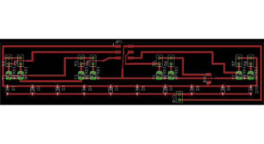
Based on these schematic designs, here are the PCB design for the three boards.
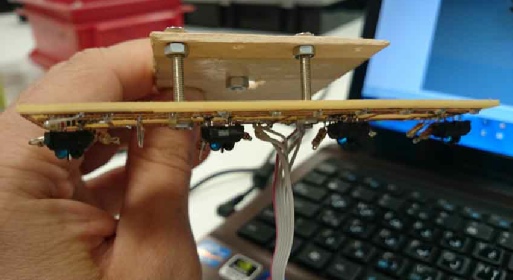
The next three pictures show the boards which are cut by our modela. Although the boards were finally cut, however I really suggest that some other methods of making boards should be introduced and used in fablab projects. Certainly, modela gives you the ability to cut boards yet the process is time consuming and inaccurate. Specially because it needs a considerably long setup time and it is very possible that the machine’s bed is not aligned, so the cutter cuts in different depths. I believe that it is almost impossible to cut a useful board with large dimensions. It is also very expensive to run this device since tips of its small cutters snap easily; so as well as loosing a cutter you have to restart the cutting again as the Z axis is set manually and it is not possible to just change the cutter and resume. It is definitely not good for making the through hole PCBs and it is also not possible to cut double sided boards with modela. If you design your boards with small traces, it will tear the traces. The cutter may also randomly cut through the traces. Basically it is a painful process to use modela in projects especially if the PCB is large or the traces are narrow and/or complicated. (PCB production took one week)
Programming
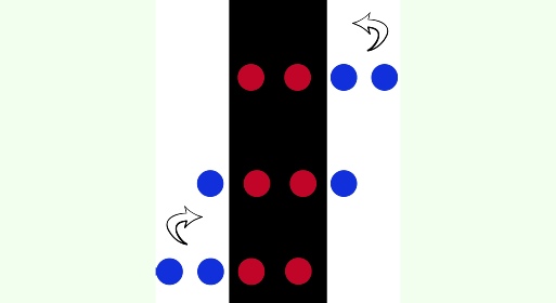
Generally the electronics design and programming aspects of this project were developed concurrently. Each field was highly influential on the development of the other one. Below is the line follower’s program and its descriptions. As it can be seen the main strategy in programming is dependent on the sensors. Basically if the two central sensors sense the black line the two DC motors will run. If at least the two left sensors sense the line, only the right DC motor runs to steer the robot to the left to hold it in the centre of the black line and vice versa. (Programming took four weeks which was done almost concurrently at the same time as the electronics design)
#include <p18f4550.h>
#include <pwm.h> // include the PWM library
#include <delays.h> // include the delay library
#include <timers.h> // include the timer library
#include <adc.h>
/* ******COMPILER DIRECTIVES FOR CHIP CONFIGURATION BITS ***/
#pragma config PLLDIV = 5 , CPUDIV = OSC1_PLL2 , USBDIV = 2 // You can write this way
// OR
#pragma config FOSC = INTOSCIO_EC
#pragma config FCMEN = OFF // OR this way
#pragma config BORV = 3
#pragma config WDT = OFF
#pragma config CPB = OFF
#pragma config CPD = OFF
//Bootloader code, DO NOT DELETE!
extern void _startup (void);
#pragma code _RESET_INTERRUPT_VECTOR = 0x000800
void _reset (void)
{
_asm goto _startup _endasm
}
#pragma code
#pragma code _HIGH_INTERRUPT_VECTOR = 0x000808
void _high_ISR (void)
{
;
}
#pragma code
#pragma code _LOW_INTERRUPT_VECTOR = 0x000818
void _low_ISR (void)
{
;
}
#pragma code
//Delay functions
void Delay1mS(int x)
{//Pre: Delay library is included.
//Post:Delay for x*1ms.
int i;
for (i=0; i<x; i++) Delay1KTCYx(12);
}
void Delay10mS(int x)
{//Pre: Delay library is included.
//Post:Delay for x*10ms.
int i;
for (i=0; i<x; i++) Delay10KTCYx(12);
}
void Delay100mS(int x)
{//Pre: Delay library is included.
//Post:Delay for x*100ms.
int i;
for (i=0; i<x; i++) Delay10KTCYx(120);
}
void Delay1S(int x)
{//Pre: Delay library is included.
//Post:Delay for x*1s.
int i;
for (i=0; i<10*x; i++) Delay10KTCYx(120);
}
#define sensors() TRISAbits.TRISA1=1;TRISAbits.TRISA2=1;TRISAbits.TRISA3=1;TRISAbits.TRISA5=1;
#define LEDs() TRISDbits.TRISD4=0;TRISDbits.TRISD5=0;TRISDbits.TRISD6=0;TRISDbits.TRISD7=0;
#define sensorsL1 PORTAbits.RA1;
#define sensorsL0 PORTAbits.RA2;
#define sensorsR1 PORTAbits.RA3;
#define sensorsR0 PORTAbits.RA5;
int result=0;
int sensorL1()
{
SetChanADC(ADC_CH1);
ConvertADC();
while(BusyADC());
result=ReadADC();
if(result>50)
{ return 0;}
else
{ return 1;
}
}
int sensorL0()
{
SetChanADC(ADC_CH2);
ConvertADC();
while(BusyADC());
result=ReadADC();
//if(result<10) return 1;
//if(result>10) return 0;
if(result>50)
{ return 0;}
else
{ return 1;
}
}
int sensorR1()
{
SetChanADC(ADC_CH3);
ConvertADC();
while(BusyADC());
result=ReadADC();
//if(result<10) return 1;
//if(result>10) return 0;
if(result>50)
{ return 0;}
else
{ return 1;
}
}
int sensorR0()
{
SetChanADC(ADC_CH4);
ConvertADC();
while(BusyADC());
result=ReadADC();
//if(result<10) return 1;
//if(result>10) return 0;
if(result>50)
{ return 0;}
else
{ return 1;
}
}
void motor_run()
{
int vv=0;
if(sensorL1()==0&&sensorL0()==1&&sensorR0()==1&&sensorR1()==0)
{
// move forward
LATDbits.LATD4=0;// motor direction
LATDbits.LATD5=1;
LATDbits.LATD6=1;
LATDbits.LATD7=0;
SetDCPWM1(800); // give new value for the duty cycle motor speed.
SetDCPWM2(800);
vv=1;
}
else if(sensorL1()==1&&sensorL0()==1&&sensorR0()==1&sensorR1()==0)
{
//stop
LATDbits.LATD4=0;// motor direction
LATDbits.LATD5=0;
LATDbits.LATD6=1;
LATDbits.LATD7=0;
SetDCPWM1(800); // give new value for the duty cycle motor speed.
SetDCPWM2(800);
vv=2;
}
else if(sensorL1()==0&&sensorL0()==1&&sensorR0()==1&&sensorR1()==1)
{
//move right
LATDbits.LATD4=0;// motor direction
LATDbits.LATD5=1;
LATDbits.LATD6=0;
LATDbits.LATD7=0;
SetDCPWM1(800); // give new value for the duty cycle motor speed.
SetDCPWM2(800);
vv=3;
}
else if(sensorL1()==0&&sensorL0()==0&&sensorR0()==0&&sensorR1()==0)
{
// stop
LATDbits.LATD4=0;// motor direction
LATDbits.LATD5=0;
LATDbits.LATD6=0;
LATDbits.LATD7=0;
SetDCPWM1(800); // give new value for the duty cycle motor speed.
SetDCPWM2(800);
vv=4;
}
else if(sensorL1()==1&&sensorL0()==0&&sensorR0()==0&&sensorR1()==0)
{
// stop
LATDbits.LATD4=0;// motor direction
LATDbits.LATD5=0;
LATDbits.LATD6=1;
LATDbits.LATD7=0;
SetDCPWM1(800); // give new value for the duty cycle motor speed.
SetDCPWM2(800);
vv=4;
}else if(sensorL1()==0&&sensorL0()==0&&sensorR0()==0&&sensorR1()==1)
{
// stop
LATDbits.LATD4=0;// motor direction
LATDbits.LATD5=1;
LATDbits.LATD6=0;
LATDbits.LATD7=0;
SetDCPWM1(800); // give new value for the duty cycle motor speed.
SetDCPWM2(800);
vv=4;
}
}
void main( void )
{
TRISB = 0xF0 ;
//1.6second.
sensors();
LEDs();
OpenADC(ADC_FOSC_2&ADC_RIGHT_JUST&ADC_1ANA,ADC_CH1&ADC_INT_OFF&
ADC_VREFPLUS_VDD&ADC_VREFMINUS_VSS,0B1010);
OpenADC(ADC_FOSC_2&ADC_RIGHT_JUST&ADC_1ANA,ADC_CH2&ADC_INT_OFF&
ADC_VREFPLUS_VDD&ADC_VREFMINUS_VSS,0B1010);
OpenADC(ADC_FOSC_2&ADC_RIGHT_JUST&ADC_1ANA,ADC_CH3&ADC_INT_OFF&
ADC_VREFPLUS_VDD&ADC_VREFMINUS_VSS,0B1010);
OpenADC(ADC_FOSC_2&ADC_RIGHT_JUST&ADC_1ANA,ADC_CH4&ADC_INT_OFF&
ADC_VREFPLUS_VDD&ADC_VREFMINUS_VSS,0B1010);
TRISC=0b11111001; // Set channel C1 and C2 as PWM output.
LATC= 0x00; // Initialize the PORTC.
TRISD=0x11;
LATD=0x11;
OpenTimer2(T2_PS_1_16 & TIMER_INT_OFF); // Timer2 is used for the time base of the PWM. set
//timer2 before PWM works.
// Set timer2 prescaler to 1:16, and set interrupts OFF
OpenPWM1(159); // PWM period =[(period ) + 1] x 4 x TOSC x TMR2
//prescaler. The value of period is from 0x00 to 0xff.
// Channel 1:PWM period = (159+1)*4*(1/48e6)*16 =
//0.21ms
OpenPWM2(159); // Channel 2:PWM period = (159+1)*4*(1/48e6)*16 =
//0.21ms
//SetDCPWM1(640); //PWM x Duty cycle = (DCx<9:0>) x TOSC x TMR2 prescaler
// Setting duty cycle for channel 1: DC = 640 *
//(1/48e6)*16 = 0.21 ms, duty cycle is 100% now
//SetDCPWM2(640); // Setting duty cycle for Channel 2: DC = 640 *
//(1/48e6)*16 = 0.21 ms, duty cycle is 100% now
while(1)
{
LATBbits.LATB0 = 1;
motor_run();
}
}
Mechanical design and assembly
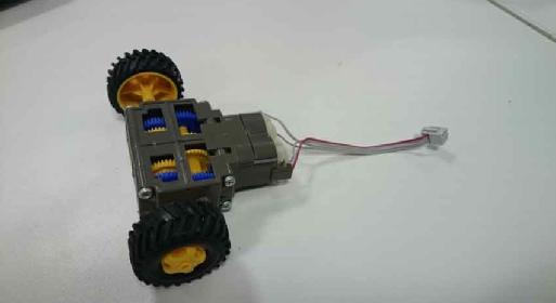
Mechanical design is a very important part of this project. This device must have two DC motors, each controlled separately in order to enable the robot to steer and find its place in the centre of the black line. Since these motors spin fast and do not produce much torque I needed a gearbox to gear my DC motors down and increase the torque. For this purpose I used a ‘double gearbox which was lying around or lab. The online price is £ 14.
The motors used in gearbox are: 9 V DC,
speed: 8200 RPM
current: 70 mA
dimensions: 31 x 24 x 18mm
weight: 37g
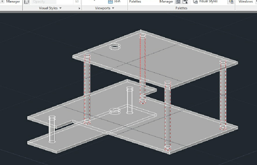
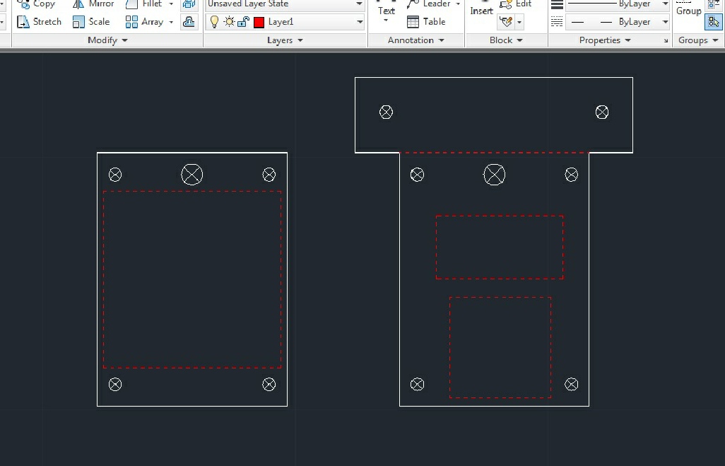
The other important part of such a project is the chassis. It has to be light and also capable of carrying the weight of the PCBs and the 9 V battery. Underneath the chassis, where the sensors’ board needs to be installed, we need to create an adjustable surface for the board therefore we can adjust the sensors to be placed in their optimum position (in this case 2.5 mm above the ground). Apart from the two wheels which are attached to the gearbox in the back there should be a free spinning wheel in the front which can facilitate the steering. For chassis I used two cuts of 2 mm plywood to form two separate levels for placing my PCBs over them; and I used knots and bolts to create an adjustable platform for the sensors.
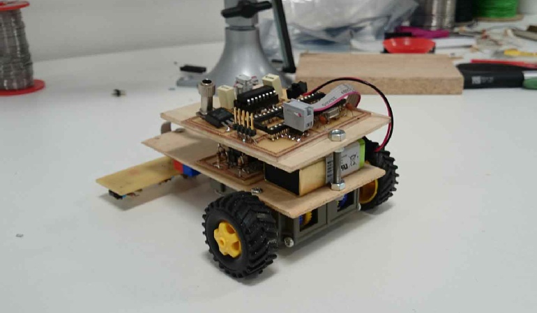
Below is the picture showing the assembled product. I agree that it does not look pretty and it has very simple design! Yet the project is open for further development. (Mechanical design and production took two days)


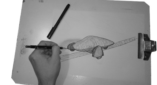
What can be changed
In total we had very limited time for developing our projects and my lack of electronics knowledge did not help it. As it can be seen in my initial sketches, what I considered as a part of my final project was to design an aerodynamic body for this robot. Unfortunately I was not able to make it and the reason was the long process of making the PCBs as it took longer than I expected. The body size was limited by the dimensions of the electronic components. Therefore one of the next possible projects can be designing and making that body which also requires a better chassis to be designed. As an example the adjustable platform could be designed in a better way which will provide more accuracy in the work of the robot.
The other improvement could be to try to make as many as possible of parts in the lab. Many components (such as the gearbox and wheels) could be fully designed and made in our fablab. Since the gearbox’s price is relatively high it is worthy to try to make it. It can also be customized for the purpose of this specific project so the sizes and function will match the product.
From electronics point of view, I think It would be interesting to add more input devices to this robot so it could for example sense obstacles or heat sources. I also could add more output devices such as speakers or monitors to add to the capabilities of my robot.
I directed most of my efforts towards designing, making and programming the electronic parts but I believe that mechanics is a very important part of this project. Without a good mechanical design all of the electronics would not work properly if not at all! Although we did not have the mechanical design until the end of the course, yet it is very essential part of most of the projects so it is worthy to pay more attention to it from earlier stages of the work. In order to design and make the gearbox by my own I need to do much further research. Therefore studying about the gearboxes and torque and designing a suitable gearbox and making one is one of my next moves in this project.
Download link for the CAD file.
Download link for the CAD file.
Download link for the CAD file.
Download link for the CAD file.
Download link for the CAD file.
Download link for the CAD file.
A quick review of the components:
The micro controller should have the necessary input and output pins to connect to the two voltage comparators and the motor driver. Basically to be able to connect to the necessary input and output devices in a line following robot.
A motor controller is device or group of devices that serves to govern in some predetermined manner the performance of dc motors [which in this case we need a motor driver to be able to manage at least two DC motors]. A motor controller might include a manual or automatic means for starting and stopping the motor, selecting forward or reverse rotation, selecting and regulating the speed, regulating or limiting the torque, and protecting against overloads and faults.
I also need to use two voltage comparators one connected to the left hand side sensors and the other connected to the right hand side sensors. Their task is to analyse the input voltage from the sensors based on the predefined parameters and then send the signals to the micro controller.
The potentiometer is needed to calibrate the sensors based on their distance to the floor surface.
The IR pairs basically consist of a sender and a receiver of infra red light. They will recognize differences between the light surface and dark lines.


Download link for the chassis CAD design.