


This week’s exercise is to link at least two micro controllers. For this purpose I am going to design two boards and connect them by wire. The min board is going to be connected to a PC using a USB port and have an input electronic component on it. Then it sends messages to the second board. The second board also receives electricity from the first board and has an output component on it. In my design I am going to use a switch on the first board as the input component and an LED light on the second board as the output component.
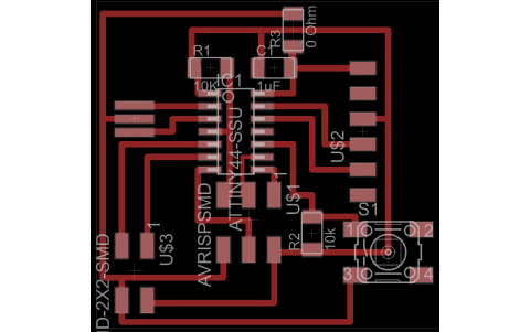
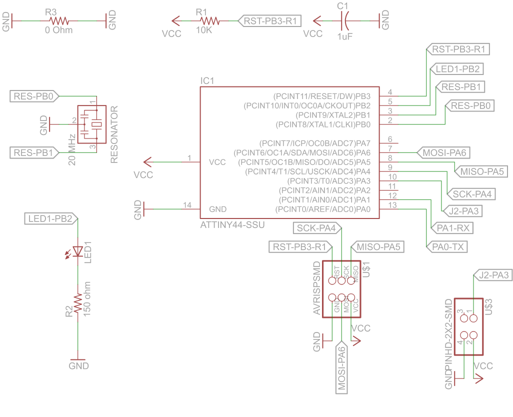
The hob board is shown in the front picture and its schematic design is shown below.
By clicking on this link you can access the board file.
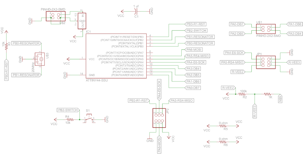
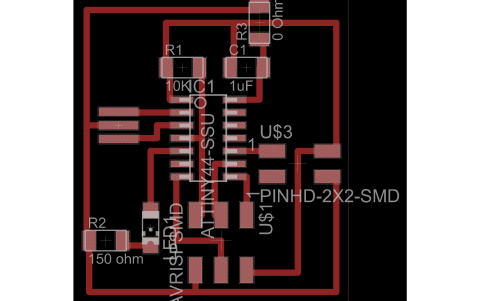
The second board is shown in the front picture and the schematic design is shown below.
By clicking on this link you can access the board file.
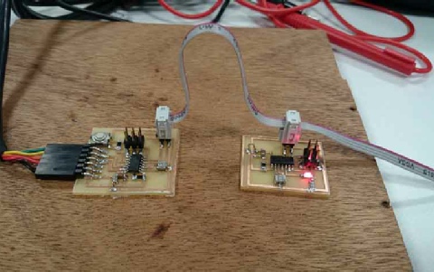
The plan is to connect the hob to the PC, connect the second board to the first one. The LED light is going to be on on the second board and when we press the button on the first board the light will turn off and goes on by releasing the button. The program accompanied by descriptions are as following:
/*
* communicationb.cpp
*
* Created: 29/05/2014 16:08:16
* Author: Maziar
*/
#include <avr/io.h>
#include <util/delay.h>
#include <avr/pgmspace.h>
#include <string.h>
#ifndef F_CPU
#define F_CPU 10000000UL
#endif
int main(void)
{
int i;
DDRA &=~(1<<PA3);// PA3 input
DDRB|=(1<<PB2); //set PB2 as output OC0A
while (1) {
if(PINA & (1 << PA3)) // check PA3 for input
{
PORTB &=(~(1<< PB2));
}else{
PORTB |=((1<< PB2));// set PBe high for communication
}
}
}
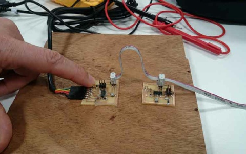
I used the same program for the two micro controllers but had to program each separately using the provided jumpers on each board. After programming the two of them realized that I made a mistake in making the connectors on the linking cable. Had to cut the connector and change the wires and try again.

By clicking on this link you can access the schematic file.
By clicking on this link you can access the schematic file.