


As I mentioned before, for each of the weekly assignments I try to cover a part of my final project which is going to be a line following robot. For design and production of an output device, a DC motor would be ideal towards my final project. The board was designed but unfortunately couldn’t have access to the required ‘motor drive’ at that time.
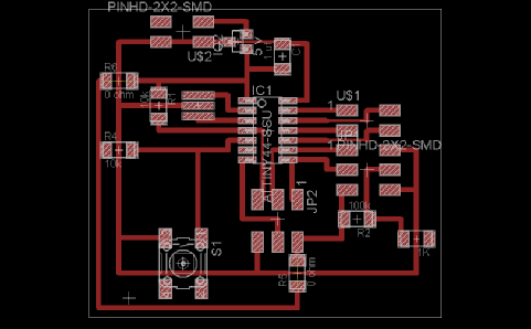
Instead tried to design a LCD device. The aim is to slightly modify the available board design and add a switch to the board. The design product can be seen in the picture.
By clicking on this link you can access the board file.
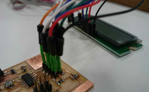
After milling out and stuffing the board, it needed to be connected to the LCD screen. Since the connector was not available at that time I managed to to connect the board to the screen using jumper wires and wire coating.
/*
* LCD_Button_p.cpp
*
* Created: 13/05/2014 21:36:21
* Author: Maziar
*/
#include <avr/io.h>
#include <util/delay.h>
//#include <UTIL/delay.h>
#include <avr/pgmspace.h>
#include <string.h>
#ifndef F_CPU
#define F_CPU 10000000UL
#endif
#define output(directions,pin) (directions |= pin) // set port direction for output
#define set(port,pin) (port |= pin) // set port pin
#define clear(port,pin) (port &= (~pin)) // clear port pin
#define pin_test(pins,pin) (pins & pin) // test for port pin
#define bit_test(byte,bit) (byte & (1 << bit)) // test for bit set
#define LCD_port PORTA
#define LCD_direction DDRA
#define DB7 (1 << PA0)
#define DB6 (1 << PA1)
#define DB5 (1 << PA2)
#define DB4 (1 << PA3)
#define E (1 << PA4)
#define RS (1 << PA5)
#define long_delay() _delay_ms(1000) // delay before redraw
#define lcd_delay() _delay_ms(10) // delay between commands
#define strobe_delay() _delay_us(1) // delay for strobe
//
// lcd_putchar
// put character in lcdbyte
//
void lcd_putchar(char lcdbyte) {
//
// set RS for data
//
set(LCD_port, RS);
//
// output high nibble
//
if bit_test(lcdbyte, 7)
set(LCD_port, DB7);
else
clear(LCD_port, DB7);
if bit_test(lcdbyte, 6)
set(LCD_port, DB6);
else
clear(LCD_port, DB6);
if bit_test(lcdbyte, 5)
set(LCD_port, DB5);
else
clear(LCD_port, DB5);
if bit_test(lcdbyte, 4)
set(LCD_port, DB4);
else
clear(LCD_port, DB4);
//
// strobe E
//
strobe_delay();
set(LCD_port, E);
strobe_delay();
clear(LCD_port, E);
//
// wait
//
lcd_delay();
//
// output low nibble
//
if bit_test(lcdbyte, 3)
set(LCD_port, DB7);
else
clear(LCD_port, DB7);
if bit_test(lcdbyte, 2)
set(LCD_port, DB6);
else
clear(LCD_port, DB6);
if bit_test(lcdbyte, 1)
set(LCD_port, DB5);
else
clear(LCD_port, DB5);
if bit_test(lcdbyte, 0)
set(LCD_port, DB4);
else
clear(LCD_port, DB4);
//
// strobe E
//
strobe_delay();
set(LCD_port, E);
strobe_delay();
clear(LCD_port, E);
//
// wait and return
//
lcd_delay();
}
//
// lcd_putcmd
// put command in lcdbyte
//
void lcd_putcmd(char lcdbyte) {
//
// clear RS for command
//
clear(LCD_port, RS);
//
// output command bits
//
PORTA = lcdbyte;
//
// strobe E
//
strobe_delay();
set(LCD_port, E);
strobe_delay();
clear(LCD_port, E);
//
// wait and return
//
lcd_delay();
}
//
// lcd_putstring
// put a null-
//
void lcd_putstring(PGM_P message) {
static uint8_t index;
static char chr;
index = 0;
while (1) {
chr = pgm_read_byte(&(message[index]));
if (chr == 0)
return;
lcd_putchar(chr);
++index;
}
}
//
// lcd_init
// initialize the LCD
//
void lcd_init() {
//
// power-
//
lcd_delay();
//
// initialization sequence
//
lcd_putcmd(DB5+DB4);
lcd_putcmd(DB5+DB4);
lcd_putcmd(DB5+DB4);
//
// 4-
//
lcd_putcmd(DB5);
//
// two lines, 5x7 font
//
lcd_putcmd(DB5);
lcd_putcmd(DB7);
//
// display on
//
lcd_putcmd(0);
lcd_putcmd(DB7+DB6+DB5);
//
// entry mode
//
lcd_putcmd(0);
lcd_putcmd(DB6+DB5);
}
int n;
int main(void) {
n=0;
DDRB &=~(1<<PB2);// ADC3 at PA3 input
//
// main
//
// set clock divider to /1
//
CLKPR = (1 << CLKPCE);
CLKPR = (0 << CLKPS3) | (0 << CLKPS2) | (0 << CLKPS1) | (0 << CLKPS0);
//
// initialize LCD pins
//
clear(LCD_port, DB7);
output(LCD_direction, DB7);
clear(LCD_port, DB6);
output(LCD_direction, DB6);
clear(LCD_port, DB5);
output(LCD_direction, DB5);
clear(LCD_port, DB4);
output(LCD_direction, DB4);
clear(LCD_port, E);
output(LCD_direction, E);
clear(LCD_port, RS);
output(LCD_direction, RS);
//
// initialize LCD
//
lcd_init();
//
// main loop
//
lcd_putcmd(0);
lcd_putcmd(DB4);
_delay_ms(1000);// delay for 1000 ms
while (1) {
while (PINB & (1 << PB2))// read the button on PB2
{
lcd_putcmd(0);
lcd_putcmd(DB4);
for(int i=0;i<=5;i++)// if the button pushed clear the screen
{
_delay_ms(100);
}
}// Otherwise put the characters on the screen
lcd_putcmd(0);
lcd_putcmd(DB5);
//
// print first line from flash
//
static const char line1[] PROGMEM = "FabLab";
lcd_putstring((PGM_P) line1);
//
// go to zero position
//
lcd_putcmd(DB7+DB6);
lcd_putcmd(0);
//
// print second line from flash
//
static const char line2[] PROGMEM = "LCD experiment";
lcd_putstring((PGM_P) line2);
}
}
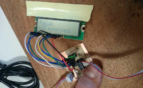
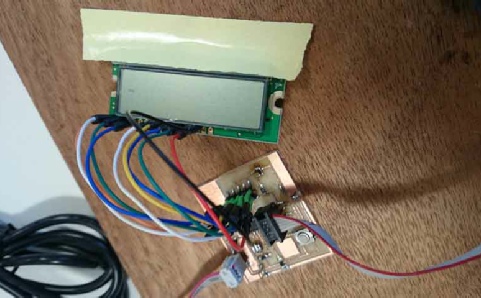
Here is the final product!
The screen is blank and when the button is pressed it shows: FabLab
LCD experiment
and becomes clear when the button is released.
As it can be seen, the program is a modified version of the fablab program.

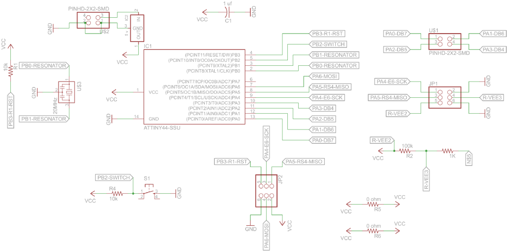
By clicking on this link you can access the schematic file.