
Since I am going to make a line following robot for my final project I believe it is appropriate to work on light sensors to design and make my input device as the hardware as well as the program would be useful in my final project.
Initially I decided to have two light sensors and two LED on my board and program it so if one side of the board is lighter the LED on the other side of the board would be lighter. Almost the logic which I will be using in my robot.
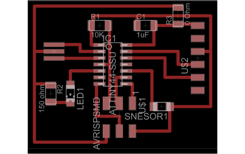
By clicking on this link you can access the schematic file.
150 ohm
LED1
150 ohm
LED2
Sensor 2
Sensor 1
0 ohm
1 uf
10k
Attiny 44
20 mhz
Unfortunately because there was not a working cutter available in our lab at the moment I couldn’t cut the board which I designed. Thus I decided to modify the ‘echo hello-
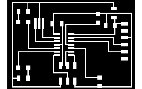
The result layout is as it can be seen in the picture.
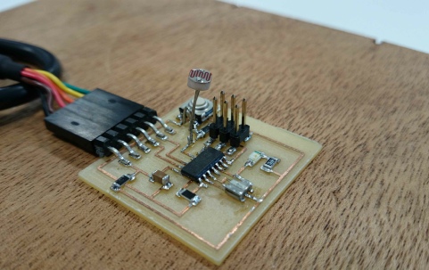
It has a sensor and a LED. When the sensor receives light the LED is off and vice versa.
By clicking on this link you can access the board file.
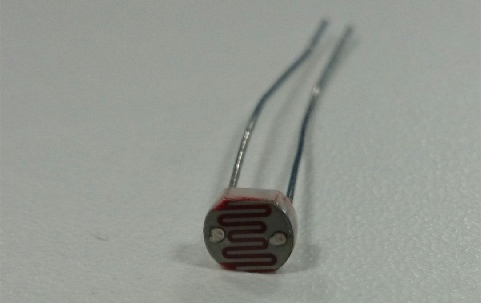
Since there is not any surface mount light sensor available in our lab at the moment I used a through hole component which worked fine in the end.
Next is the program. Below the program and descriptions of each line is demonstrated:
/*
* light-
*
* Created: 07/04/2014 16:41:06
* Author: Maziar
*/
#ifndef F_CPU
#define F_CPU 20000000UL
#endif
#include <avr/io.h>
#include <UTIL/delay.h>
#include <avr/interrupt.h>
#include <stdint.h>
#include <math.h>
void initADC(void)// initialize analog to digital conveter
{
DDRA |=(1<<PA3);// ADC3 at PA3 input
ADMUX |=(1<<MUX1)|(1<<MUX0); //select ADC3
ADMUX &=~((1<<REFS1)|(1<<REFS0)); // VCC as reference voltage
ADCSRB |=(1<<ADLAR); // left adjust for 8 bit resolution
ADCSRA |=(1<<ADEN);
}
void initPWM(void)// initialize PWM
{
DDRB|=(1<<PB2); //output OC0A
TCCR0A = (1 << COM0A1) | (1 << WGM00);// phase correct PWM mode
//TCCR0B = (1 << CS01);// clock source = CLK/8, start PWM
TCCR0B |= (1 << CS01) | (1 << CS00);//// Set Timer 0 prescaler to clock/8.
TCCR0A |= (1 << WGM01) | (1 << WGM00);// Set to 'Fast PWM' mode
}
int main(void)
{
double val;
initADC();// call ADC initialization
initPWM();// call PWM initialization
DDRB|=(1<<PB2); //set PB2 as output OC0A
while(1)
{
val=0;
ADCSRA|=(1<<ADSC); // start conversion
while(ADCSRA&(1<<ADSC)); // wait conversion to be completed
val= ADCH; // value of the ADC
if( val>0)// check the ADC value and response correspondingly
{
OCR0A=0;
}else
{
OCR0A=255;
}
}
return(0);
}
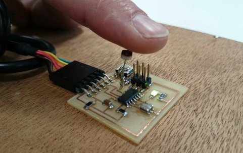
Here is the end product. The two pictures show the board when it receives the light and when it doesn’t.