Input devices
I do not come from the world of electronics.
It was hard for me to understand all of the sensor world works
and the way it interacts with the computer.
I decided to continue with the arduino software.

I knew a little bit of the processing software anf knew that
the two works good together.
.jpg)
before designing a new board I wanted to first understand how
does the sensor works with the arduino borad. I worked with a touch sensor:
First, I attached the sensor through a bread board to an arduino uno board:
after I did this I searched for an example which can connect the sensor with the
arduino and processing, in the arduino site I found this coeds for arduino and processing:
sensor for arduino and processing
I copied the arduino code from the link into my arduino software:
after I copied the arduino code I copied the processing code into the processing software:
After doing this I had two codes ( in arduino and processing which can work together )
this means that the output the arduino software recieves from the arduino board translates in
the computer as words.
after emmbeding these codes, the processing takes the output from the
arduino board and can translate it to agraphic image.
I have no knowledge in writing arduino or processing codes from skretch so I wanted to mix some
codes together in order to create something interesting.
I went to the processing examples> Colors> Hue:
Now that I had two codes to mix I had to realize what is relevant for the sensor to change the hue
colors which are forming in my computer.
the knock sensor code made the connection between the arduino board to the processing.
in the original Hue example code the mouse of the computer was in charge to change the colors:
I knew I wanted to replace the mouse with the arduino board, here is the code I created:
/**
* Draw color bars using touch sensor
* Author : Gali Blay
*/
import processing.serial.*;
String buff = "";
int val = 0;
int NEWLINE = 10;
int whichBar =0;
int SCREEN_WIDTH = 640;
int SCREEN_HEIGHT = 255;
int BAR_WIDTH = 10;
int NUM_OF_BARS = SCREEN_WIDTH / BAR_WIDTH;
int colorValue =0;
Serial port;
void setup()
{
size(SCREEN_WIDTH, SCREEN_HEIGHT);
colorMode(HSB, height, height, height);
noStroke();
background(0);
// Open your serial port
port = new Serial(this, "COMXX", 9600); // <-- SUBSTITUTE COMXX with your serial port name!!
}
void draw()
{
while (port.available() > 0) {
serialEvent(port.read());
}
}
void serialEvent(int serial)
{
if(serial != NEWLINE) {
buff += char(serial);
} else {
buff = buff.substring(1, buff.length()-1);
// Capture the string and print it to the commandline
// we have to take from position 1 because
// the Arduino sketch sends EOLN (10) and CR (13)
drawBar();
println("The input value is: " + buff);
// Clear the value of "buff"
buff = "";
}
}
void drawBar(){
whichBar = (whichBar + 1) % NUM_OF_BARS;
int barX = whichBar * BAR_WIDTH;
colorValue = (colorValue + + 5) % 255;
fill(colorValue , height, height);
rect(barX, 0, BAR_WIDTH, height);
}
/**
after I created this I saw that the delay in the sensor is too high,
probably becuase of the diffrences of th esensors,remeber, this coed
was written for a knock sensor and I used a touch sensor.
Hence, I changed the delay in the arduino code:
this is what I created from the combination of the codes:
touch sensor with arduino and processing from gali blay on Vimeo.
When I realized how the sensor works and how it works with arduino and processing
I felt confident enough to design a special board for the sensor.
I went back to anna's tutorial from the electronics design week:
eagle-electronics design
I took Anna's Hello button board and redesigned it as a touch sensor board in illustrator.

here are the PNG images ready to mill,the trace file:
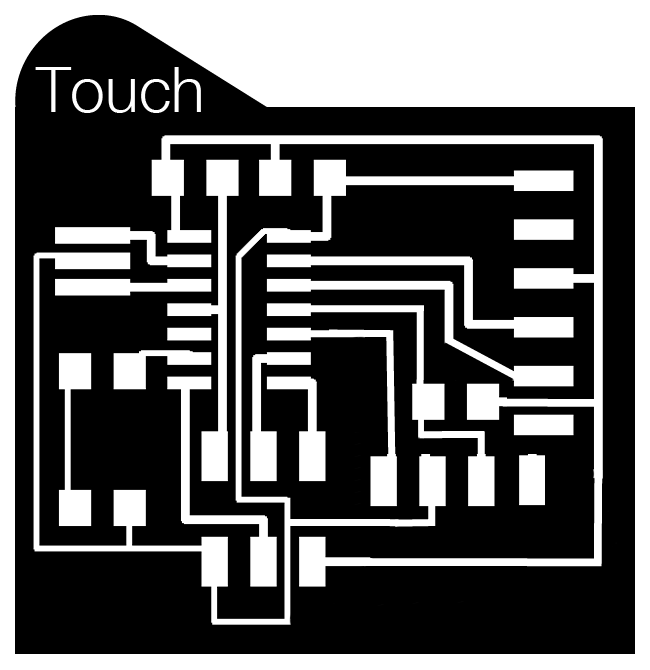
The interior file:

This is how it looked like after I milled and soldered it: