Week 3. Computer-controlled cutting
Third week of the FabAcademy, and this means it is time to start to play with the machines.
This week the lesson was about computer-controlled cutting with several kind of machines, as
vinylcutter or lasercutter, and the assigment to desing, make and document a press-fit construction kit.
Designing the structure
The first part of the assigment consists on design something you can build with
a computer-controlled cutting machine and that you can afterwards assemble. This means it was time
to remember the concepts learned previous week and design something with your favorite software.
To make the design I used OpenSCAD as I feel very confortable with it after
the first assigment. Also, from what Neil explained in the class and thanks to the advice of my instructor
Nuria, I learned
that it is very common that you need to modify some parameters of the design to make the parts assemble in a perfect
way, so a parametric software is the optimal solution.
You can see below a snapshot of OpenSCAD tool with the first design I did for this assigment, and you can
download the file here. I decided to set as parameters the thickness
of the material, the size of the holes and a certain offset to reduce the size of the holes and make the
pieces attach as if they were glued.
From the design to cutting the pieces
Once the original piece was designed, it was time to buil it on cardboard using the Epilog Laser
Cutter available at Fablab León. This machine was not able to process the OpenSCAD files, so to print
my design I needed before to translate it to .dxf format, and later edit it on Rhinoceros to
define the cutting parameters.
To export from OpenSCAD to .dxf file was not so easy as expected, but after a bit of search through
internet I find a solution:
- Create your 3D design in OpenSCAD, render it and export it to .stl format.
- Create a new file in OpenSCAD with the sentence: projection(cut=false) import("/STL/test1.stl");, where
in import you indicate the path of your file
- Render this new file and export it as .dxf
Once I had my desing on .dxf, it was time to import it on Rhinoceros and select the different parameters
of cutting. To define the lines to be cut, the line width was set to less than 0.01mm, and for the graver lines
it was set a line width bigger than 0.25mm.
For the remaining parameters, as speed, power or frequency of the laser, it was very useful for me some
examples of pieces that are available in the FabLab, so I set:
- For cutting:
- For graver:
- Speed: 100%
- Power: 80%
- Frequency: 500Hz
|
I send it to the printer, and after one print, the cardboard was not fully cut, and I needed to
print it twice. This make me thought that maybe the paremeters needed to be readjusted, so to cut
deeply, I decreased the speed in a 20%, but I got the same results.
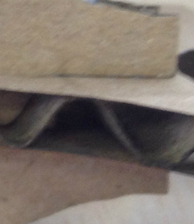
After thinking about it and discussing with Nuria, we got to a conclusion: maybe the air space
between the two surfaces of the cardboard is not leting the laser to cut it properly, so we decided
to go to de orginal parameters and ask the laser to cut twice all the lines with very good results.
|
|
In the images below you can see the comparison between the front and back part of the cardboard
using one and two paths with the laser.
|
Front part. There is not signigicative difference between
the piece cut once and cut twice.
|
|
|
Back part. You can see that the piece cut once. Although
the speed was lower, it was not cut on the back part.
|

|
Once the problem with cutting the cardboard was solved, it was time to try to assemble the pieces
together, but... surprise!! The pieces were not assembling correctly as the joints were too loose. It
was the time to come back to OpenSCAD and modify the size of the holes, making the smaller, to make
the pieces keep joined.
Redesigning and parameters tuning
The redesign process was an iterative process, were some parameters were modified in the design, the
new pieces printed, but some problems or points of improvement were detected. In the table below there is
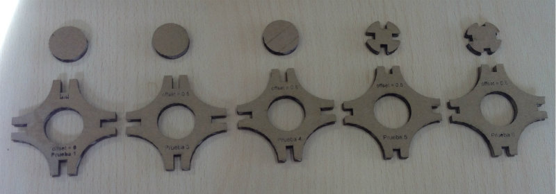
a summary of the different designs and the parts improved.
|
Design #1
|
Original design. The size of the holes is identical to the cardboard width.
|
|
Design #2
|
In the original desing it was identified that the joints were too loose, so it was
decided to make the holes smaller, so the pressure to assemble the pieces must be higher.
|
|
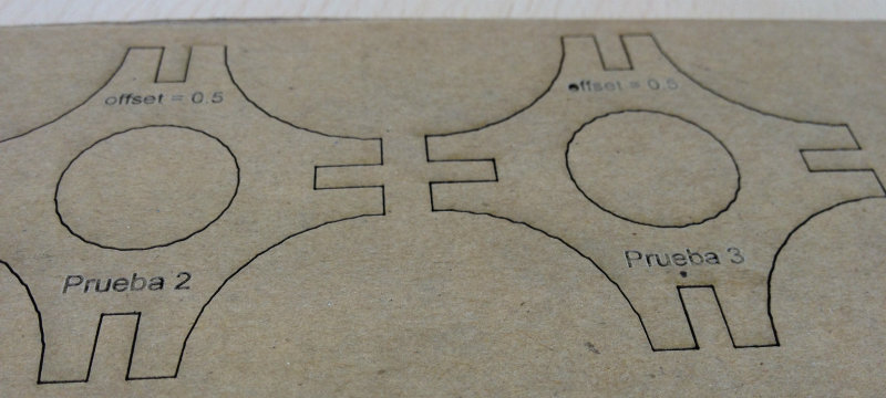
Design #3
|
After design 2, the joints were tighter, so the pieces stand by themselves. The problem was the
sometimes the flaps were damaged in the assembling process, so it was decided to include some
flanges as Neil commented in class.
|
|
Design #4
|
Later, I realized that the circle extracted from the middle could be used as a union
between the pieces. Anyway, to get that, the size of the holes must be smaller to avoid
collisions, and some marks in the circle will be useful for the assembling.
|
|
Design #5
|
The holes introduced in the inner circle were to big if we wanted to join two pieces
in ortogonal direction, so they were reduced
|
You can also download the .dxf file edited in Rhino and ready to print in the Epilog lasercut
here.
Once the final design of the individual parts was finished, it was time to put the lasercut to
work and do many of them to be assembled in a funny way.
The final construction
Pieces, pieces and more pieces. It is time to think about different ways to assemble the pices.
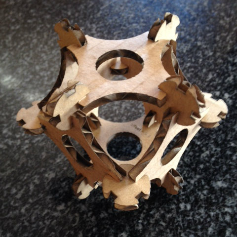
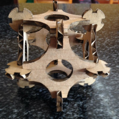
After some tests, assemble and disassemble several times, I end up with many different structures.
The first structure I made with the pieces it was a cube you can see below:
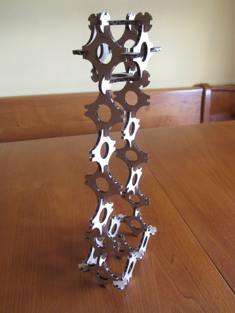
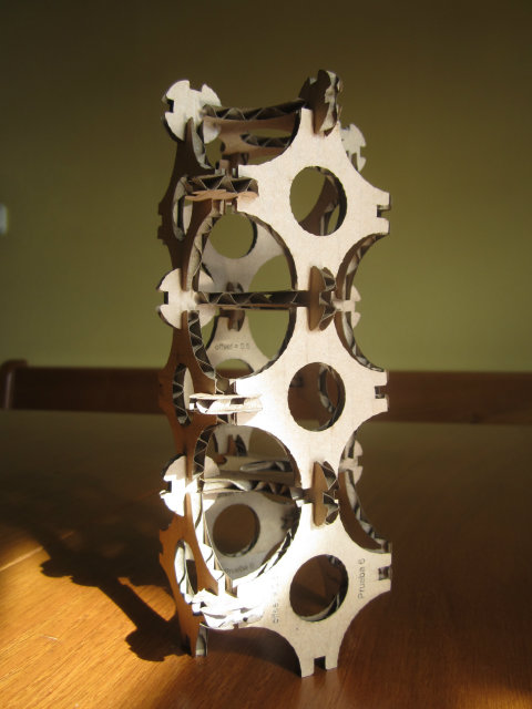
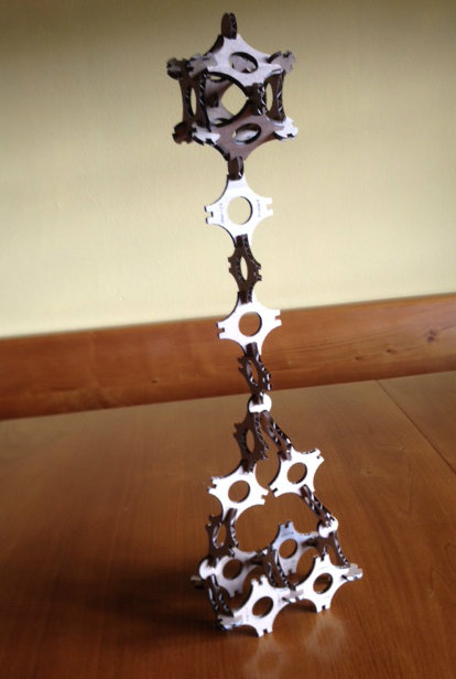
Then I saw that the structure was quite consistent, and the joints were very robust,
so I decided to go for something bigger and higher, and I built these towers you can see
in the pictures below. Some of them were closer to 1 meter high.