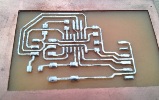
The assignment consists of the designing a board. This board has a button and a LED in it.
Here you can see the Video where you´ll see the "schematics" of many boards, including the embedded board EAGLE
const int buttonPin = 5;
const int ledPin = 6;
int buttonState = 0;
void setup() {
pinMode(ledPin, OUTPUT);
pinMode(buttonPin, INPUT);
}
void loop(){
buttonState = digitalRead(buttonPin);
if (buttonState == HIGH) {
digitalWrite(ledPin, HIGH);
}
else {
digitalWrite(ledPin, LOW);
}
}
CONST INT LEDPIN means the number of the pin of LED.
The CONST keyword stands for constant. It is a variable qualifier that modifies the behavior of the variable, making a variable "read-only". This means that the variable can be used just as any other variable of its type, but its value cannot be changed. You will get a compiler error if you try to assign a value to a CONST variable
VOID SETUP. This function is called when a sketch starts. Use it to initialize variables, pin modes, start using libraries, etc.
PINMODE. Configures the specified pin to behave either as an input or an output. See the description of digital pins for details on the functionality of the pins. The pin: the number of the pin whose mode you wish to set. The mode: INPUT, OUTPUT, or INPUT PULLUP.
VOID LOOP. After creating a setup() function, which initializes and sets the initial values, the loop() function does precisely what its name suggests, and loops consecutively, allowing your program to change and respond.
BUTTON STATE turn on and turn off.
"IF" is used in conjunction with a comparison operator, tests whether a certain condition has been reached, such as an input being above a certain number.
DIGITALWRITE includes pin (pin number) and value (HIGH or LOW).
PARAMETER |
VALUE |
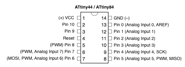
FLASH (KBYTES): |
4 KBYTES |
PIN COUNT: |
14 |
MAX. OPERATING FREQ. (MHZ): |
20 MHZ |
CPU: |
8-BIT AVR |
# OF TOUCH CHANNELS: |
6 |
HARDWARE QTOUCH ACQUISITION: |
NO |
MAX I/O PINS: |
12 |
EXT INTERRUPTS: |
12 |
USB SPEED: |
NO |
USB INTERFACE: |
NO |
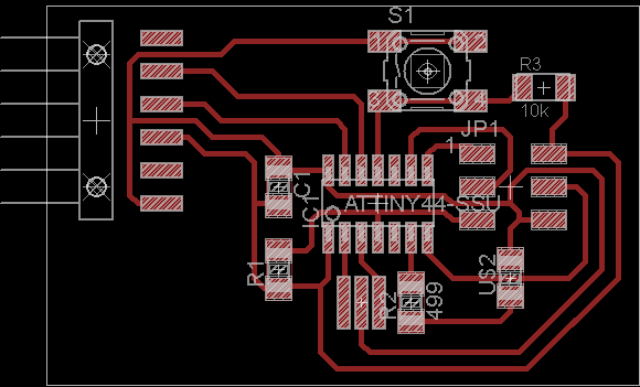
This is the schematic, made in EAGLE
Click the "Скачать" button for downloading
The original code is this one:
//Include Files
#include<avr/io.h>
#define F_CPU 128000UL
#include<util/delay.h>
int main(void) {
DDRB |= 1<<2|1<<3;//Declare as outputs
PORTB |= 1<<2|1<<3;
//Switch off the LEDs
DDRB &= ~(1<<0|1<<1);//Input declared
PORTB |= (1<<0|1<<1);//Pull up Enabled
while(1){
//switch1
if(!(PINB&(1<<0))) //If pressed
{
_delay_ms(10);//debounce
while(!(PINB&(1<<0)));
//wait for release
_delay_ms(10);//debounce
PORTB^= (1<<3);//Toggle
}
//switch2
if(!(PINB&(1<<1)))//If pressed
{
_delay_ms(10);//debounce
while(!(PINB&(1<<1)));
//wait for release
_delay_ms(10);//debounce
PORTB^= (1<<2);//Toggle
}
}
}