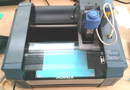
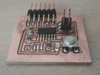
| IMAGE 1 |
EXPLANATION 1 |
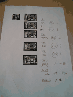
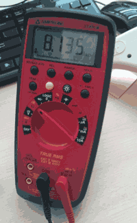
IMAGE 2 |
EXPLANATION 2 |
 |
EAGLE
Eagle is a program that provides a quality PCB design. We´ll use a schematic editor and we´ll load the fablab library and the Niel´s library to have a number of neccessary components. |
 |
Open the Eagle Window. Download the fab libraries from the folder. |
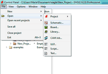 |
Then push the "File" button -> "NEW" -> "Schematic" and start working
If you already have any project saved in Eagle folder, "OPEN" it from the folder.
So, what we are going to do is to search for all neccessary components, that consist of: |
 |
- Microcontroller Explanation
- LED of 1.8 V
- Capacitor
- Resistance 1k and 10k
- Resonator or a Crystal
- FTDI (connector)
- AVRISPSMD
- A button
|
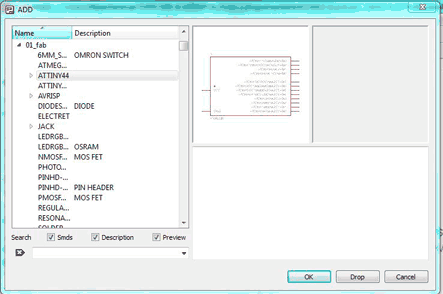 |
Let´s start! Open "Edit" -> "Add" -> Look at the names of libraries you downloaded and select one of them. First of all, look for the microcontroller "ATTINY44", insert it. |
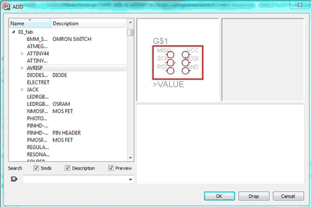 |
Then, search for the AVRISP in 01_fab |
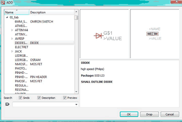 |
DIODES from 01_fab library |
 |
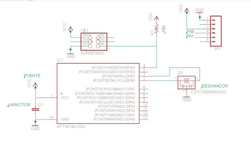
So, when you found all the components (I wasted like an hour to find all of them) just draw "NET" lines, not "WIRE" lines. Every connection has an extention as net line. |
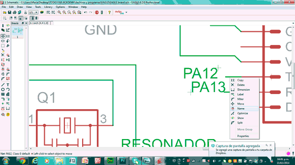 |
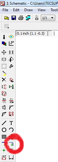
Then, you are to give them a name. The scheme will help you. Select an option "move" on the left side on the screen. Then select the line you want to name. Select "name" option. |
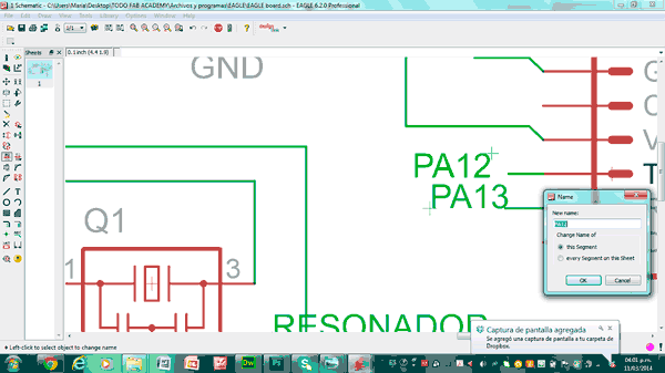 |
After that, write the name of PIN you will connect with resistance with LED, and the button. |
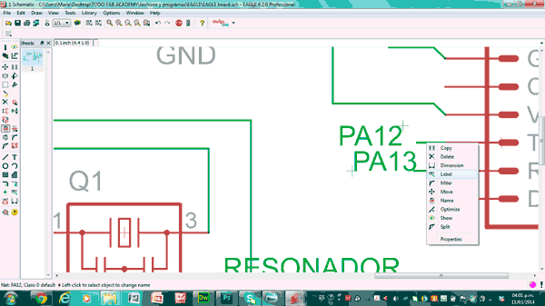 |
To give the name to a PIN push "label" it. |
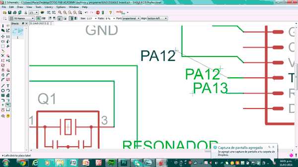 |
The PIN´s name will appear |
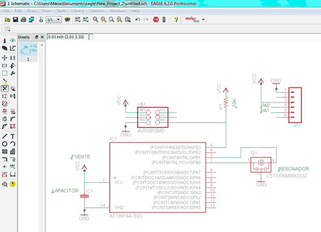 |
Mark all the Pins and connections. And then select "schematic" on the top of control menu. It has a symbol of "sockets". |
 |
Here is the result. All the connections are created correctly. What we´re going to do now is to organize them to make an electric structure. |
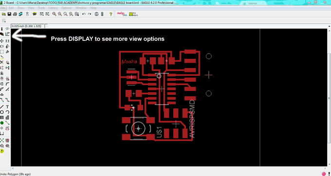 |
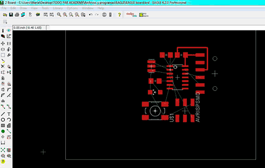
The DISPLAY options permit you to see where are all the components situated. Select "place", "name" and "origin" options. |
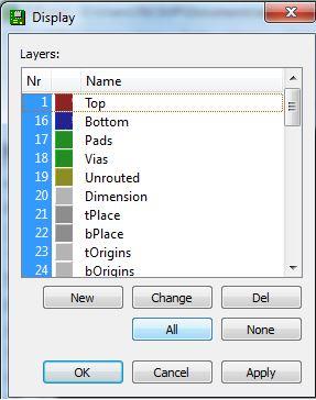 |
Push "NONE" and select "TOP", "BOTTOM" and "DIMENTIONS". Push "OK". We block all the electronic components to be able to export the image for Roland Modela. We need only pins and vias of the circuit. |
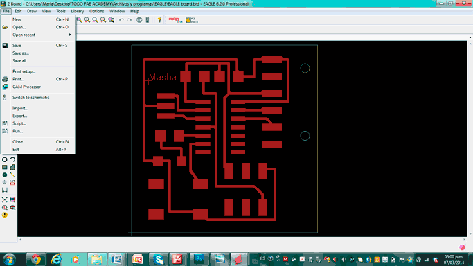 |
Here we go!
Push "FILE", "EXPORT", "IMAGE". Then select "MONOCHROME", 600 dpi, and the folder to save in. |
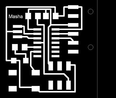 |
I exported the image. Watch the Video to make sure you understood the process.
NB: This border you can eliminate deselecting "dimentions" in the"display" option. If you want the different border you can eliminate this white square. Chose any geometrical form: circle, rectangular, a line.
|
How to use the voltimeter? On the left you´ve got ampher measuring. At this way you measure the "I" bulk flow of the electrons. On the right - volts. You measure the voltage.