ASSIGNMENT IV ELECTRONICS PRODUCTION
Watch the tutorial SOME TIPS FOR SOLDERING
INTRODUCTION This assignment consists in making an electronic controller for arduino. To do this we need: Roland Modela cutter, a plaster board, soldering iron, a magnifying glass, powerful lamp, heating element, tweezers, Tin wire and the board elements.
This assignment consists in making an electronic controller for arduino. To do this we need: Roland Modela cutter, a plaster board, soldering iron, a magnifying glass, powerful lamp, heating element, tweezers, Tin wire and the board elements.
| Modeling Functions | |
| Tool chuck | 6 mm or 1/8 in. tool chuck included |
| Spindle motor | 10W (DC motor) |
| Software resolution | 0.025 mm/step (0.000984 in./step) |
| Mechanical resolution | 0.00625 mm/step (0.000246 in./step) |
| Revolution speed | 6,500 rpm |
| Feed rate | 0.1 to 15 mm/sec. (0.00393 to 9/16 in./sec.) |
| Acceptable material | Wood, Plaster, Resin (modeling wax, styrenform), Chemical wood |
| Acceptable tool | End mill, Drill |
WATCH THE VIDEOS: HOW TO WORK WITH EAGLE?
1  2
2 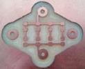 3
3 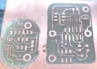 4
4 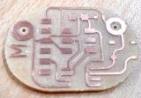
These are the modified boards of some assignments. As you see the first ones are well-cutted and the last one have some vias crushed. 1) LCD board; 2) LEDS; 3) Button board; 4) LCD (modified second time) and Button board. Sometimes I had to sand some boards. Later I´ll give you some tips to have no problems with Roland Modela.
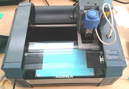
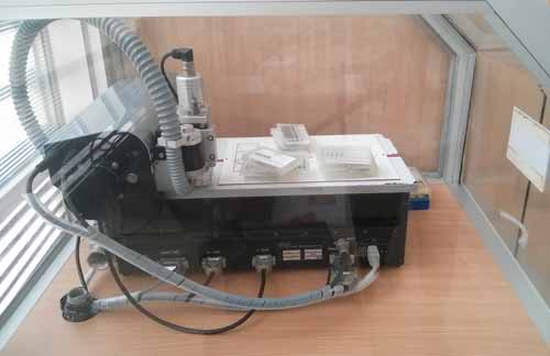
THE ROLAND MODELA is appropriate to work with wax, plastics and wood. It has different tools of diverse dimensions. The nozzle we used is 0.4 mm. It´s quite easy to manipulate this machine. First of all you´ve got to remove the plastic cover and to place the plaster board. There are several squares of 1 cm on the board that help you to measure the X and Y parameters. X is horizontal and the Y is vertical. Secondly, put an adhesive tape to the bottom of the plastic board and it on the surface of Modela, calculating the number of squares. For example, I chose 6 for X and 3 for Y because at this position it´s more easy to see the moduling process.
We also could have used this machine ProtoMat C40 that is specially designed for the circuit cutting. Unfortunately, still the software is not installed. So, that´s why we did not use it.
HOW TO USE THE ROLAND MODELA
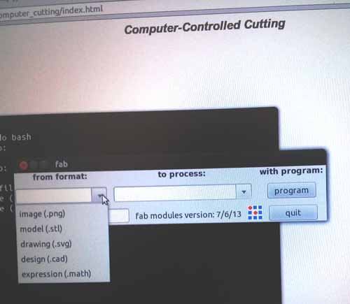
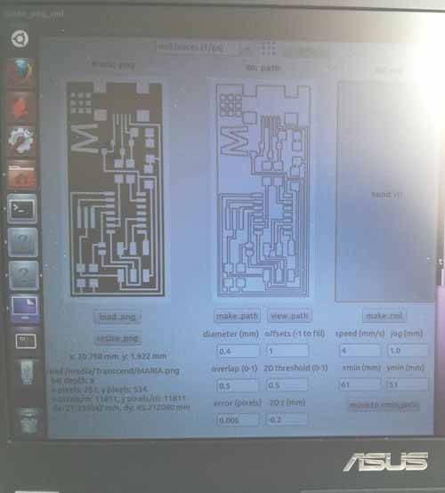
Modela´s software is easy to use. Just open Ubuntu and introduce in Terminal "sudo bash", and then "fab". In "format" window choose the option "image (.png) and in "process" window put Roland Modela (.rml). Then push the botton "make_png_rml" for the next step.
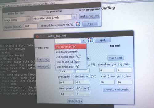
Now, choose the option "mill traces (1/64)". To load your circuit picture press "load.png" and it will appear on the left of the screen.
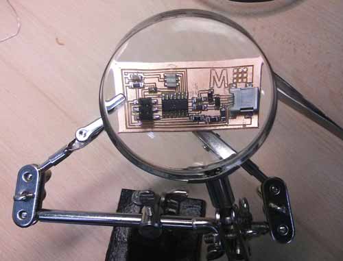
To personalize your board, you also can include any image you like. As for me, I´d like to have my owl on it. Unfortunately, the drawing is too complicated, it has too much lines. When milling it on the board, all the details will desappear. So, that´s why I changed it to "M" design. It´s the first letter of my name.
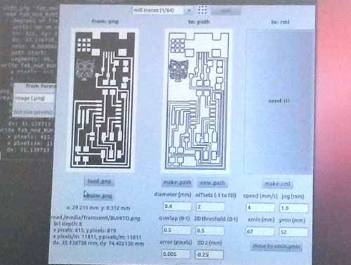
So, the recommended milling parameters for 1/64 are: 1) diameter 0.4 (nozzle diameter); 2) offsets 1 (how many times repeat the cut); 3) overlap 0.5; 4) 2D theshold 0.5; 5) error 0.0005 (the error margin) 6) ZDz (mm) -0.1 (the depth of cut).
Then you´ve got to establish the point of origin. When we are ready to cut the board, press "make.rml" and then "send it".
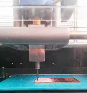 The time of cutting is aproximetly 4 minutes.
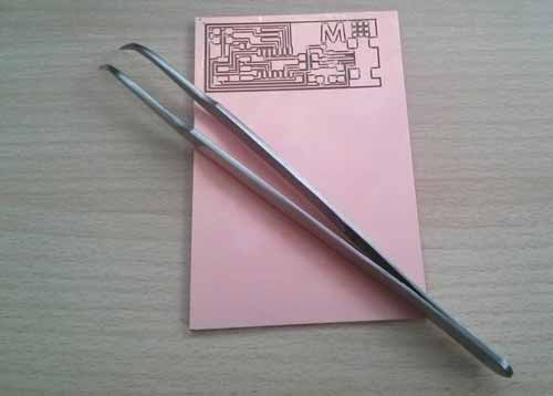 Sometimes in the board channels remains plastic dust that could distrurb us while soldering. That´s why you should clean it with a rigid brush and if it´s not sufficient, use tweezers.
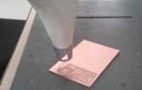 After cleaning the board, we are to cut unnecessary plastic part. There are different ways to do it: with the same Modela cutting, Laser machine or hand cutting. I chose the last one. So, you are to heat the plastic board from both sides for 3 minutes.
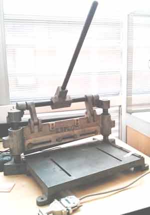 Then put your heated board under the knife. The copper side of the board put down on the metal zone to not damage it. Push the lever and cut the board softly.
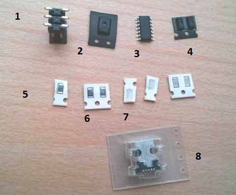
Next step is to solder all elements of the board. Let´s see what they are one by one. 1) Connection with AVR; 2) Cristal; 3) Integrated circuit; 4) Resonators; 5) Resistance 4990; 6) Resistance 1000 (two units); 7) Resistance 0; 7.1) Resistance 1001; 7.2) Resistance 1002; 8) USB connector.
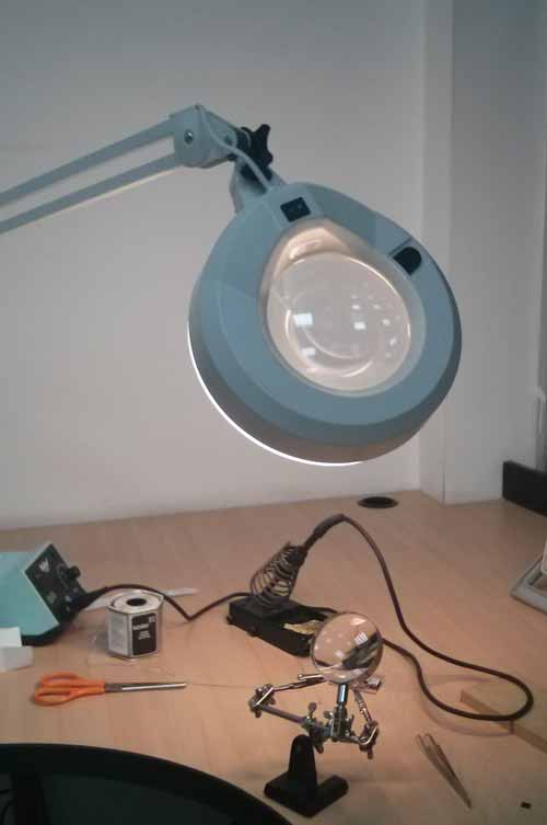 To solder all electronic elements I needed a magnifying glass with some clips to sustain the board, a powerful lamp to have sufficient light and the solderig iron (20Watts) which is heated till 550 Fx.
 SOLDERING PROCESS
You´ve got to work carefully.
Firstly, put a little bit of stannol-soldering grease where all electronic elements should be placed. Secondly, press the tip of soldering iron to the working area and wait 5 seconds.
SOLDERING PROCESS
You´ve got to work carefully.
Firstly, put a little bit of stannol-soldering grease where all electronic elements should be placed. Secondly, press the tip of soldering iron to the working area and wait 5 seconds.
Thirdly, heat the tin wire with soldering iron such a way to leave a little drop of the tin (1-2mm). Don´t put too much Tin (Sn), because you can pollute the channels and othe parts of electronic board. Fourthly, place the electronic element to its position and press it with the soldering iron. I recommend you to have a little bit of tin on the tip to solder better. When you finish, you´ve got to connect your board to usb port and to AVRISP2.
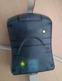
When connected, the red light should turn green. It means that there is an electricity in the circuit.
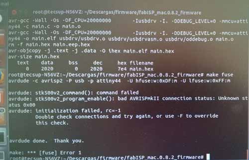
After completing all the programming steps, the error appeared. Lately I´ll explain what steps I have taken to program my "M" board. The reason could be the short circuit or bad-soldered parts.
 While taking a break, I met this nice cat in the Coffe house.
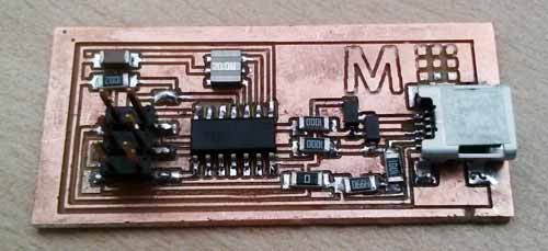
I made a NEW board!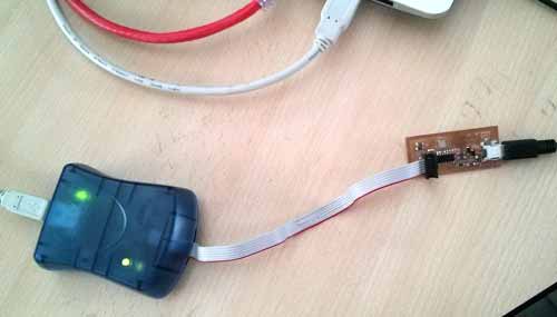 This one also gives a green light.
HERE IS THE PROGRAMMING EXPLANATION
After connecting my new electronic board to the AVRISP2, I opened the Terminal in Ubuntu. What you´ve got to write? 1) "Sudo Bash"; 2) Location of the folder "downloads". 3) "Make clean"; 4) "Make hex"; 5) "Make fuse"; Done! 6) "Make program" Success! 7) "lsusb" 8) Fabtiny. In the end fabtiny has to appear.
With this board I programmed the INPUT DEVICES! PLEASE, PROCEED TO THE PAGE OF INPUT DEVICES. Thank you.