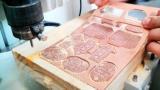
Due to the fact that the Roland Modela is not designed for the constant and long work. May be we could not calibrate it well. As for example, the Modela of another Fablab functioned well. But there they did not use the option 1/32, only 1/64 to not force the machine.
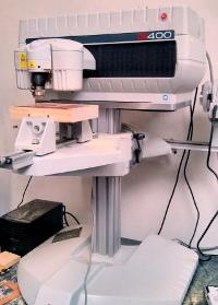
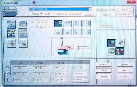
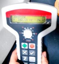
Here you can see the software of Gravograh "TYPE3" in peruvian ZOLID.
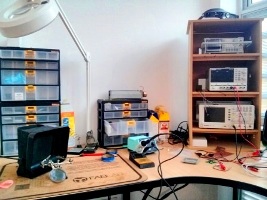
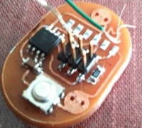
HOW DID I CONNECT ALL THE ELEMENTS?
1)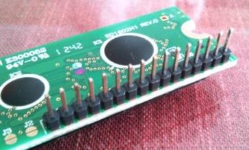
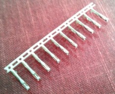
Firs of all solder an Through hole connector. You`ll need 10 PINS
2) 
3) 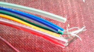
Take some cables and remove the cover.
4) 
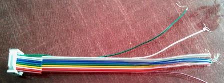
Put the cable into the connector and press it to fix. Then solder it! You`ll need just a drop of a tin.
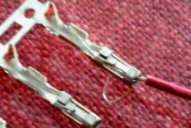
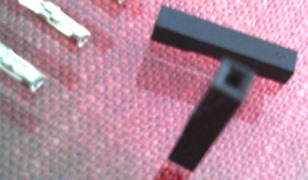
Cut this metalic connector. And solder the next cable.
5) 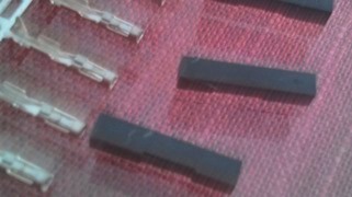
Then insert these fixing heads.
6) And the last step is to connect all the cables to the LCD`s PINS.
PROGRAMMING PROCESS
- First, go to the page THE FAB ACADEMY and download MAKEFILE
- HERE IS THE CODE OF NIELS
PROJECT=hello.LCD.44
SOURCES=$(PROJECT).c
MMCU=attiny44
F_CPU = 20000000
CFLAGS=-mmcu=$(MMCU) -Wall -Os -DF_CPU=$(F_CPU)
$(PROJECT).hex: $(PROJECT).out
avr-objcopy -O ihex $(PROJECT).out $(PROJECT).c.hex;\
avr-size --mcu=$(MMCU) --format=avr $(PROJECT).out
$(PROJECT).out: $(SOURCES)
avr-gcc $(CFLAGS) -I./ -o $(PROJECT).out $(SOURCES)
program-bsd: $(PROJECT).hex
avrdude -p t44 -c bsd -U flash:w:$(PROJECT).c.hex
program-dasa: $(PROJECT).hex
avrdude -p t44 -P /dev/ttyUSB0 -c dasa -U flash:w:$(PROJECT).c.hex
program-avrisp2: $(PROJECT).hex
avrdude -p t44 -P usb -c avrisp2 -U flash:w:$(PROJECT).c.hex
program-avrisp2-fuses: $(PROJECT).hex
avrdude -p t44 -P usb -c avrisp2 -U lfuse:w:0x5E:m
program-usbtiny: $(PROJECT).hex
avrdude -p t44 -P usb -c usbtiny -U flash:w:$(PROJECT).c.hex
program-usbtiny-fuses: $(PROJECT).hex
avrdude -p t44 -P usb -c usbtiny -U lfuse:w:0x5E:m
program-dragon: $(PROJECT).hex
avrdude -p t44 -P usb -c dragon_isp -U flash:w:$(PROJECT).c.hex
- HERE IS THE CODE WE NEED
PROJECT=hello.LCD.44
SOURCES=$(PROJECT).c MMCU=attiny44 F_CPU = 20000000 CFLAGS=-mmcu=$(MMCU) -Wall -Os -DF_CPU=$(F_CPU) $(PROJECT).hex: $(PROJECT).out avr-objcopy -O ihex $(PROJECT).out $(PROJECT).c.hex;\ avr-size --mcu=$(MMCU) --format=avr $(PROJECT).out $(PROJECT).out: $(SOURCES) avr-gcc $(CFLAGS) -I./ -o $(PROJECT).out $(SOURCES)
program-usbtiny: $(PROJECT).hex avrdude -p t44 -P usb -c usbtiny -U flash:w:$(PROJECT).c.hex program-usbtiny-fuses: $(PROJECT).hex avrdude -p t44 -P usb -c usbtiny -U lfuse:w:0x5E:m
- The rest of the code is destinated for anthor controller, as for example the mk2.
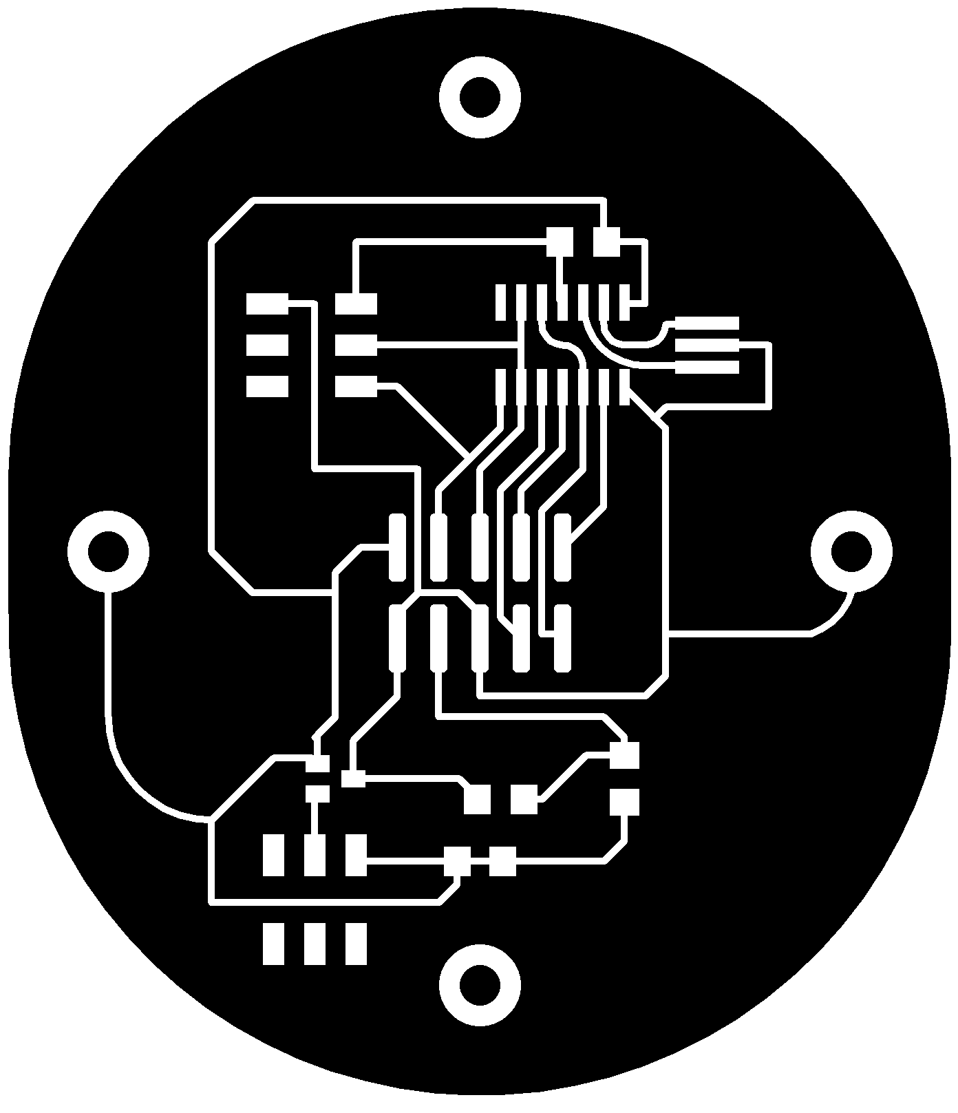
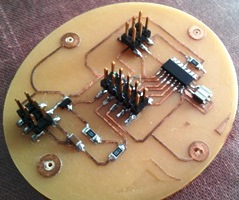
All my boards that you can see on the photo were cut in 8.5 minutes.
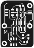
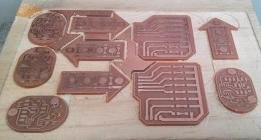
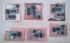
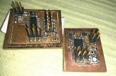
The first one is the initial work in the beggining of the academy (not modified) and the second photo demonstrates that I¨ve modified the boards. It demonstrates my skills of working with Eagle.