Fab Academy 2014
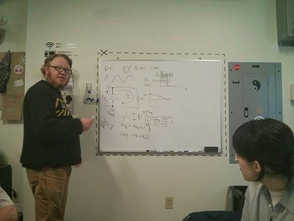
The day after Neil's lecture, Shawn gave us a really good crash course in basic electronics. Although I took a brief electronics lab as part of college physics, I really needed brushing up, and Shawn gave some great explanations. I was a little late to class, but Peter shared his notes with me on Google Drive, which was a godsend. I really need to remember to start bring the graph paper notebook I bought to class, as I'm still getting hampered by not having pencil and paper to write down ideas and make sketches. A key takeaway from Shawn's mini-lecture was the analogy of circuits as water running through a pipe. I'd heard this before, but it's always good to review the basics since I get confused easily with electronics jargon. Here goes:
- Voltage - the water pressure, the force or potential of the electrons rushing through the circuit.
- Amperage - the speed of the water, the current. This is related to the amount of electrons you could use at any one instant. Expressed in amps
- Watts - the amount of water you are using. This would be AxV.
- A circuit is fundamentally the connection between a positive source and a negative.
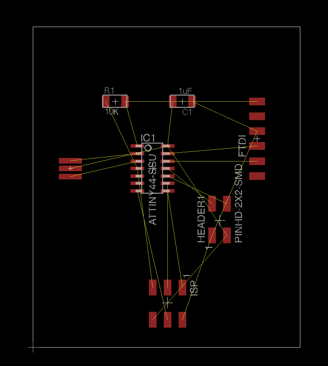
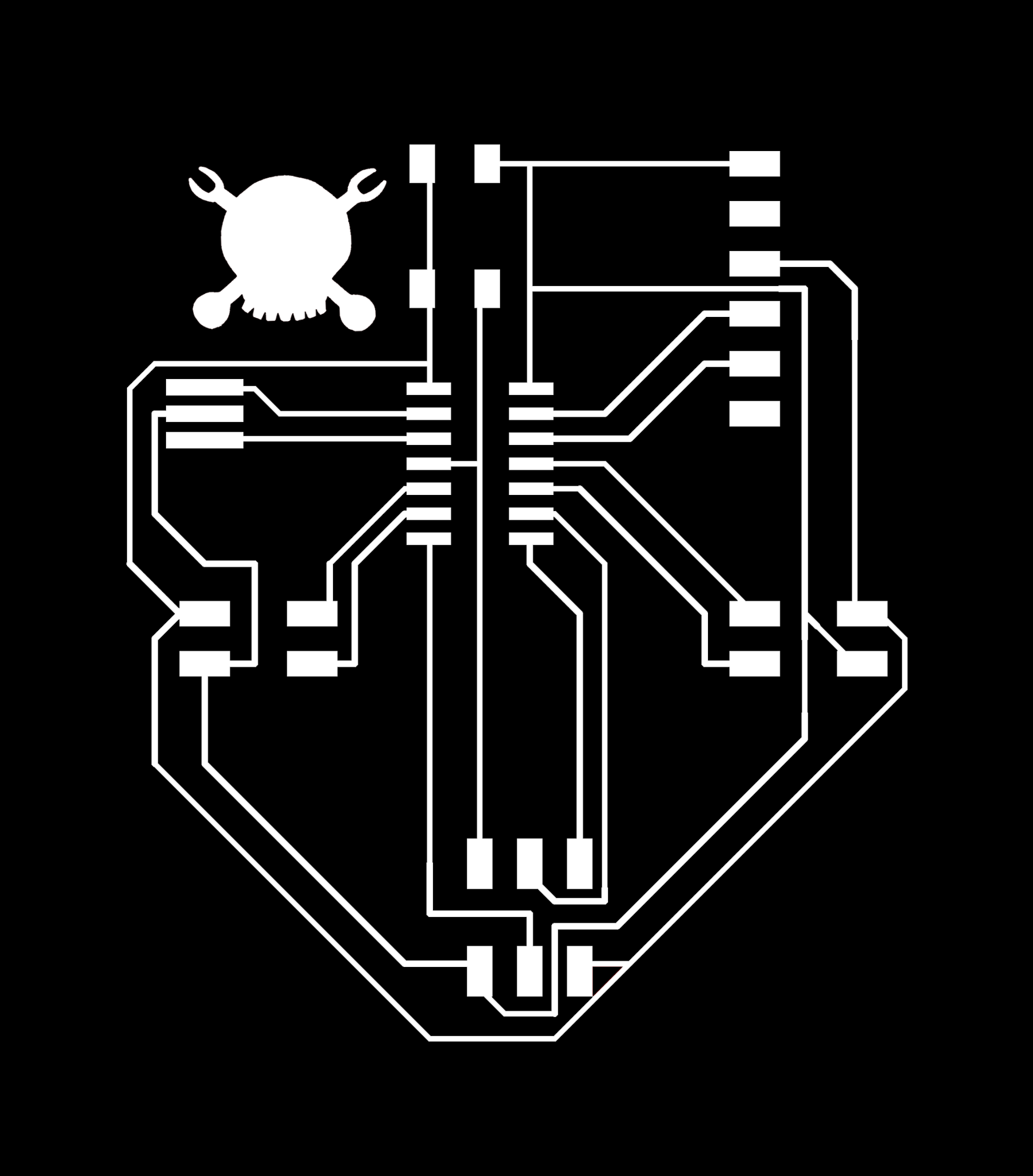
Then it was time to start designing our own boards. I started with Neil's board as a reference, but Nikolas and I decided that rather than make a board with a button and LED, we wanted to use all the available pins on our microcontroller to make connections for breakout boards. This way we could design modular boards that could connect and test out various sensors/buttons/LED setups. Although I think it could easily be really frustrating, I like Eagle. I was able to get a board up pretty quickly in schematic view, and then went on to board view to get my traces done. Initially adding the headers for the traces seemed like it was going to necessitate some 0 Ohm resistors to jump over stuff, but I was able to work it out. Here are my takeaway tips:
- In schematic view, I found it easier to just name parts (typing commands is awesome), then label them to make connections. You can sort of do this in batches and make a lot of connections really easily without having to worry if the nets are connected.
- In board view, I ended up using the auto routing option, then undoing and rotating or moving any parts that had trouble. This way I could get a nicely set up board while adjusting everything to where I wanted it quickly (notice that I kept my pieces pretty far apart to make soldering easier). There are nice menus in the auto routing option that will let you control thickness, path type, etc.
- Once I had let auto route do the best it could, I lay down my final traces manually as I adjusted the components to their homes. Here, it was useful to adjust the grid settings, and work from .05 inches, to .025 for the closer traces. This is still above the diameter of the modela's milling bit.
tried to kept the reasonator as close to the microcontroller as possible
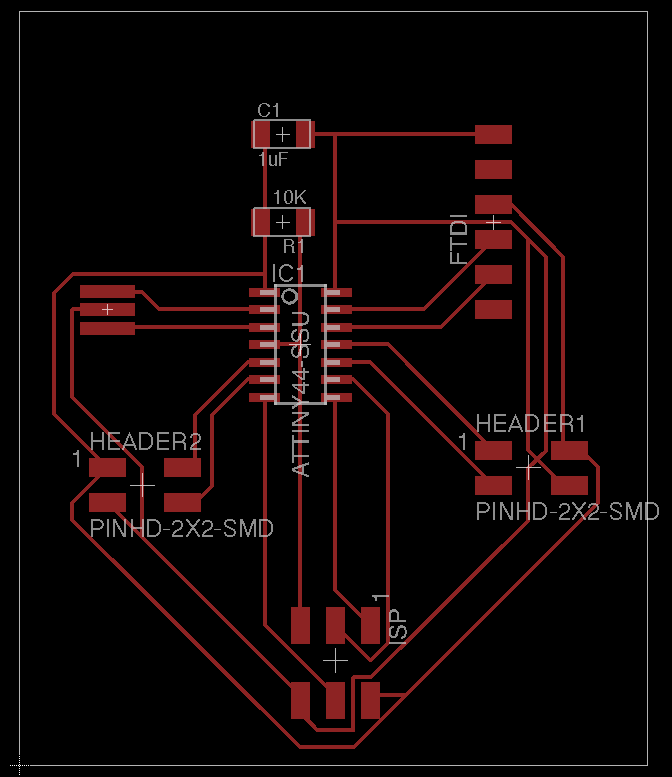
The traces up between header 1 and the FTDI are also crossed as an artifact of auto trace.
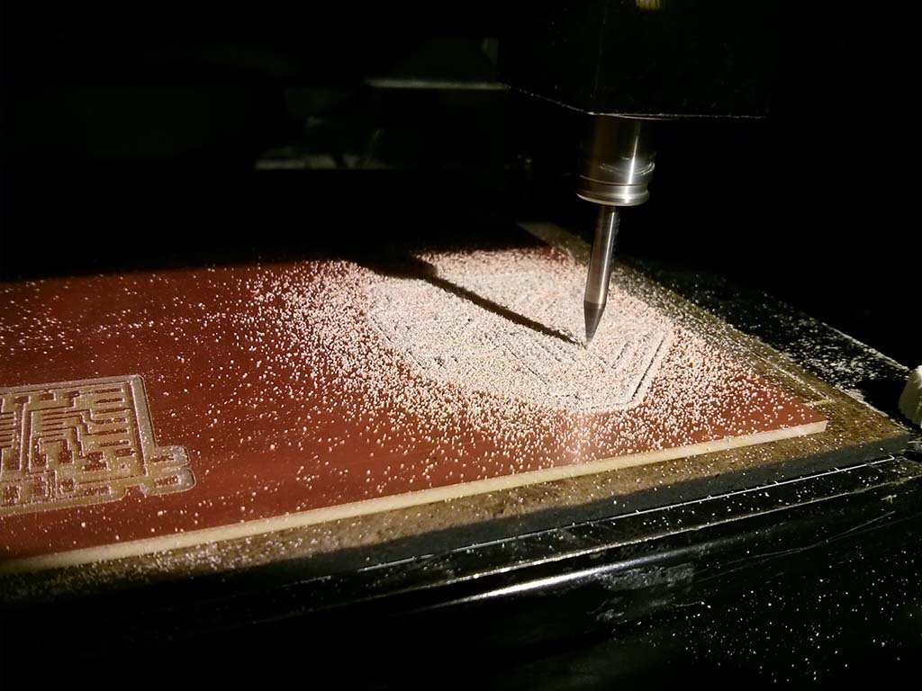
Reran the ERC and DRC (great features), and everything checked out. Got to class a little bit earlier and started milling out my board with Damien. Unfortunately, ubuntu crashed on the modela PC and after a reset I think I was off by 10 mm the first time I set my startx (we were milling together on one sheet of copper), and my first board was ruined. Good opportunity to practice setting the z axis on the modela (had to pull it down more completely to touch the board), and getting pieces cut. The second attempt was much more successful.
Soldering the board this time was a bit more difficult than last week. I initially forgot to put flux on the microcontroller as well, which made that trickier and I was left worried about my connections. However, after getting all the pieces down the fuses checked out and we were able to get a basic arduino program (the 'Blink' intro).
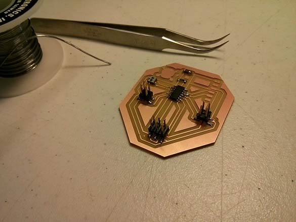
I didn't have time to mill out a breakout board (although I've got a design started for one with an RGB LED and a button). Shawn had told us that the microcontroller limits current with it's own internal resistors though, so I was able to test the program by just touching a red LED directly to the leads on the header (in this case power and pin 3 in arduinospeak on the microcontroller). It worked!