| Assignements: Design a 3D mold, machine it, and cast parts from it |
Why would I design and make a mold, in the first place?
In the context of my native place (let me put forth this is not regionalism! Just refering to the best know context), I think of situations where
multiple people have similar needs of physical pbjects. Simplest example could be mobile phones.
Some strikingly importnat examples could be hearing aid and prosthetic legs. Other common examples could be enclosures for devices. So there is a case!
Making a mold is useful, it seems.
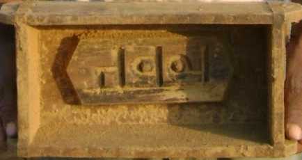
There are multiple ways to makes molds, as I could observe over various web pages. The most common mold that I've seen India, is the one used for making of bricks. It is not only common, but mainly available in such a way that most of us do not even realise the technological component in there. But then that is what we anyway need - People utilisiung things that they need, naturally, and not driven by Technology. It is a subject of discussion - when we say Technology, we are talking about just one of the components out of life around!
|
A simple, hand-made brick mold. |
| A search for open source logo png provided with many files, out of which I chose a medium size, clean PNG file. This PNG file was Imported in inkscape. Inkscape asks whether to Embedd the image or to link the image. As I am dealing with only one image at this point, I select "Embedd". | |
| Importing the PNG file, brings the logo in inkscape environment. One may have to resize the image in order to fit it inside the default page size in Inkscape. | |
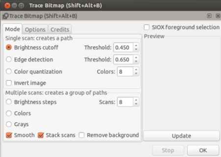 |
Trace the bitmap in order to produce curves for the input image.
Inkscape uses Potrace bitmap tracing engine, to trace the bitmap into a path element.
The default settings seem to be sufficient to produce a fine
trace. One might have to "Remove Background" by checking the corresponding option. Ofcourse, there can't be an autotracer that will produce an exact copy of the original image. With PNG or RAW format it has perhaps the best possibility. Using a JPG file produced out of same PNG, will result into a lessened quality trace, as JPG is a lossy compression that reduces the sharpness of the input image, meaning edges in the original image become blur. To trace the image: in inkscape go to path->trace bitmap |
 |
At this point, I Exported the output as Plane svg file and exited from inkscape to move on to blender (I remember the days I used to be afraid of Blender and now I am just waiting fo it to open). |
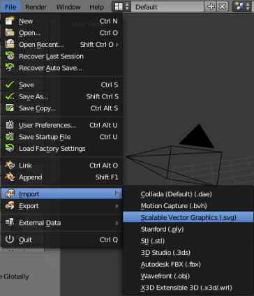 |
Initiatin the design in Blender I was wondering, how and why blender will take in a 2D image. Blender being a 3D Modelling software, it did not make much clear to me, why it will allow a 2D image to appear! Ofcourse, as soon as "import SVG" option became visible to me I could guess - it can be converted to a 3D object! So, File -> Import -> Scalable Vector Graphics (SVG) allowed to import the Open Source Logo in SVG format that I had traced in Inkscape |
|
 |
What's next Imported SVG file is flat and has no width. This is just the first step. This is obviously not printable. Next steps involve - 1) Convert this 2D object to a 3D object 2) provide dimensions to and extent enough (this is w.r.t. the application as well as the base available) |
|
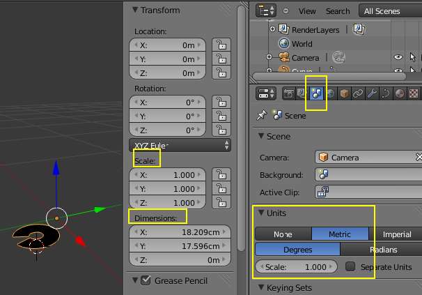 |
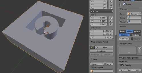
Set blender environment As the task here is to design an object that is going to take shape in real life, Blender now has to talk in terms of realisable Units. By default blender is set for Blender units (BU). 1 BU = 1 M. This can be verified by changing the Unit settings, as shown in the image. Scene -> Units -> Metric. To change this to mm, the scale will have to be changed to 0.001 as 1 corresponds to Meter. At thus point it is also logical to set the scale of the drawing to 1. To do this press ctrl A ans click on scale. A few basics on Blender: 1) There are two modes of operation in blender. Object mode and Edit mode. Both the modes have their own importance. For example an object can be selected and moved from its place, in Object Mode. While in Edit mode individual elements (e.g. vertices) of the object, can be selected and moved.
|
|
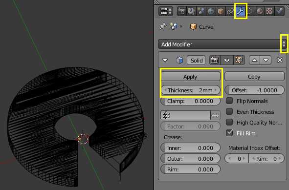 |
Make it a realisable model Blender provides with various "Modifiers" that can be applied to the selected objects. For example, creating a holein a solid cube, or joining to different objects and so on. One of the modifiers is called "solidify". As its name suggests it solidifies a given object. That means a 2D image can be provided with a 3rd dimension in order to form all the walls, making the object look like a real time entity. As shown in the image, the solidify modifier was applied to the 2D open source logo, to build a 3D object. Ideally at this point desing would almost be ready. The "thickness" parameter can be changed in order to ,odify the 3rd dimension. Also, under "Properties" (short cut key - n) all the 3 dimensions can changed, includoing their interrelations. In my case, the solidifier caused the errors highlighted by red colored boxes. The red box at the bottom of image depicts that while changing the thickness an extra extrusion took place, changing the overall shape. This is a function of "tarcing the bitmap" using inkscape. I am not sure yet how to correct this while in Inkscape, however, three different efforts generated different extrusions of this type. This was the lowest level of distortion. So next task was to remove the extrusions. A Blender user can do this in Blender itself, however, I was willing to try out NetFabb. To do so, a ".stl" file was exported using blender.
|
|
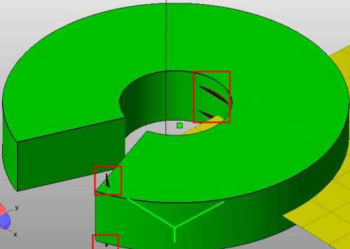 |
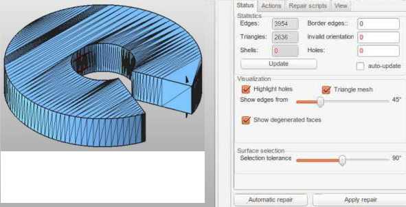
Edit the Model in NetFabb Basic Netfabb Basic is a free (not open source) software, for mainly editing meshes. It does allow adding the basic shapes, however, it is mainly used for editing the meshes, in order to make design 3D printable - bridge the gap between content and Machine. In case of my design, I "open"ed the .stl file that was exported using Blender and it looked like this. The red boxes show flaws in the design, which I wanted to remove out here, in netfabb basic (considerably rich tool, even in its free form). To do this "Repair" tool becomes an entry point. |
|
|
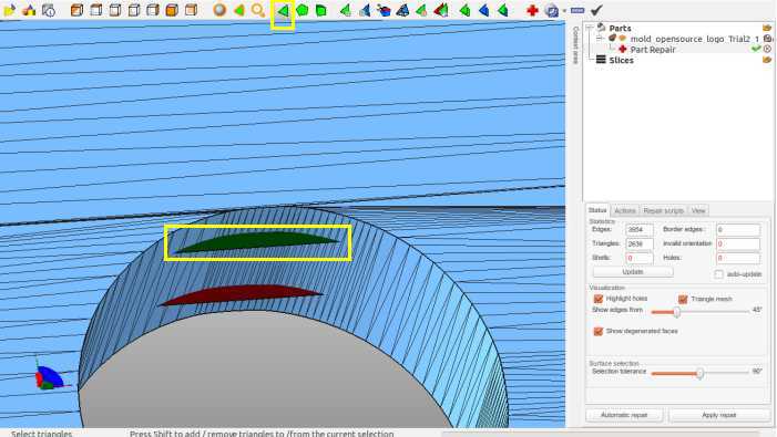
Repair the Model in NetFabb Basic In this view the Triangular mess in visible. The repair mode can be invoked by pressing the Red Coloured "+" button or Extras -> Repair First image depicts the default settings, which I did not change at all. The second image shows editing in action. The yellow square at the top of image shows the tool to be selected - edit triangles Then the next yellow box depicts what happened when I selected a sibgle triagle. The view clearly shows that there are two unwanted extrusions, which I selected one after the other and deleted by pressinf delete button. Each trangle when selected turns into green as shown in the image. Also, pressing shift key enables multiple select in order to select multiple faces, if need be. This way all the extrusion (unwanted ones) were deleted. Now, saving the model in this state does not help!! It Just saves the project! So, now is the time to press automatic repair->default repaire->Execute->Apply repir->remove old part (or keep old part) to see a clean model. |
|
 |
Export as stl and make a mold Last part is to export this file as .stl file. In that "stl" and "stl (ascii)" are the options. The "stl" type produces a low sized binary file, while the "ascii" type preducess a higher sized file. It is an observation that Fabmodules expects the first type of file. |
 |
The Fabmodules is the key to initiate mold creation process. Once the Fabmodules is
started, I selected "stl" against "from format" and ".rml" against "to process", meaning I wanted to create the mold, using stl file that was created using blender
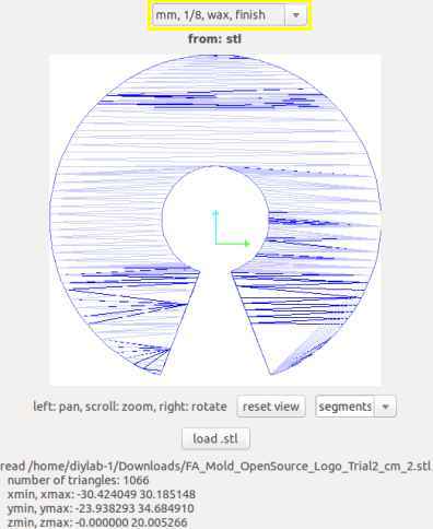
and pass it on to Modela, for milling it out on a machineable wax. So, I loaded the stl file to Fabmodules. Note the image besides. The Yellow box shows up a crucial point. (Note* Read "Rough" instead of "Finish", in the image.) Problem 1 - Many a times I selected "inches, 1/8, rough" and pressed "make png". This resulted in a hung machine! I could see on terminal that something was happening in code but eventually, it all got hung. Solution After a few trials I realised that I am confusing with dimensions of my model and dimensions of the bit. It seems, the "inches" string stands for model size and NOT for the bit size. Atlease using this logic solved my issue. So, I selected "mm, 1/8, wax, rough". And that did not hang my machine, and moved ahead to the next level. |
|
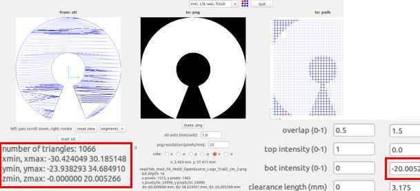 |
The Image besides (if clicked onto and seen) shows two important data-sets. The
original .stl file was generated into blender, with certain dimensions. The Red boxes in this image depict the dimensions that Fabmodules can see. As a designer
one has to make sure that the dimensions match. And they did match in my case. The second box depicts the depth, this machine is going to go till. Note* Had these numbers been different, I would have gone back to blender, adjusted the dimensions (in blender press 'n' )and mainly scale (in blender press ' ctrl+A ' and click on ' scale '), regenerated the stl and then again loaded here in Fabmodules, to see the expected dimensions. |
|
 |
After I sent the job for milling to Modela, it went just fine for arounf 1 hour,
post which the milling bit made a Low-Frequency (bass) sound, as if it was not able to drive the job and I had to "Abort" the job.  I could not make why it would do
so, however, good thing was it happened only at almost end. Perhaps only a few last few runs were remaining. I have not yet understood why this happened though.
I could not make why it would do
so, however, good thing was it happened only at almost end. Perhaps only a few last few runs were remaining. I have not yet understood why this happened though. |
|
 |
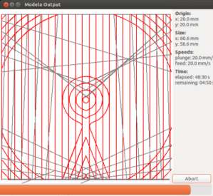
Then(after aborting), I still went ahead to the "finish" type of cut
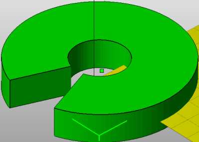
in Fabmodules to see the output shown in the image aligned here. The Finished Cut went through without me needing to abort. Problem 3 - HOWEVER!!! this was the time when I realised the biggest mistake in my design... not before this!! It is clear from the image that if I create a negative mold out of this, it will be a set of broken pieces, to be glued to each other. This realisation was to late, but worth its value, as I did not have even the slightest idea of what mistake I was doing, since the start!! Solution So going back to blender to modify this positive mold in order to have enough space around the model. |
|
 |
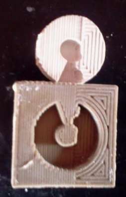
As of now (Apr 28, 2014) the .stl file is ready to be used for milling to create the Positive Mold. | |
 |
During this trial, I followed the same procedure with Modela, as described
earlier. The design was modified using Blender, also to identify non-manifold objects. Fabbbasic was also used to check the design
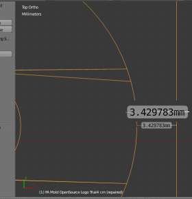
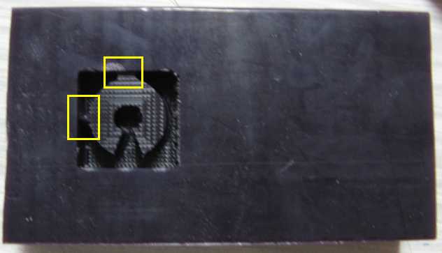
(whether it was water tight or not). The output has come out to be as shown in the image. Problem 4 The yellow insets depict the problem. These two places on this positive mold are linked to the outer box. Solution 4 The lengths of these walls (links between outer box and the curvature of the logo) are around 2.41mm and 3.07mm respectively. These numbers are smaller than the diameter of milling bit (3.175 mm)
This only means I did not pay attention to the minimum distances before molding and need to do the it again, without any carelessness. |
As said earlier, I had to modify the mold, in order to correct the distances between logo and the
walls of the mod, so that the mill bot passes through. This seemingly simple change took me some time.
I had to redesign the mold, because just
scaling the previous did not solve problem. In the previous design, though 3D model in blender seemed fine, scaling it to greater size (in order to increase
the distance between wall and the logo) had the expected effect,
eventually causing too big a size to be milled on the machinable wax blocks, we have here. That also revealed that perhaps my 3D model was not upto the mark,
not customisable enough to make minor changes. So, time to redesign...
 |
This time Following two approaches were taken up, out of which the second
one is being finalised now 1) The common background work - In the the 3D model of logo was created in Blender (already explained). Then around it a single plane was added ( Add -> Mesh -> Plane ), which was extruded ( press 'e' ) slightly above the 3D logo. At this point it seems like a completed mold (assuming the distances are safe enough). However it is not. The model is not yet watertight. Now, I "subdivided" the "bottom face". To do so one has to go to edit mode (tab), then select the bottom face, extrude it to some extent, Go to Basic in MEsh Tools and click on Subdivide, as many times as this bottoom face is subdivided in subfaces , which one can extrude individually so as to form the outer wall, thick enough (in my case - 4mm). At this point, because the plane was built around the logo, the whole look and feel is as if the mold is integrated and ready. Almost there... but not yet .... The two separate objects are to be integrated together, now. To do so, there are two methods, that I can think of - "Boolean Union" and "Join". 2) Mold by Union - A boolena union seems obvious, when to integrate two objects. And it does work in Blender ( Modifer -> Boolean -> Union ). I did this, and checked for "non-manifold objects". To my pleasant surprise, I had built a clean 3D Model!! As usual, to check if this model is good enough (manifold), I planned to use netFabb basic and exported stl from blender. Problem 5 - Importing this stl to netFabb throws up "Invalid STL file: < * >.stl" and then meshlab could also not import this stl file. Solution 5 - Eventually, I realised that after completing the mold, I had exported only One of the 2 objects. Hence, not the complete mold. However, a question still remains - why atleast that object was not recognised? At this point I was completely stuck and multiple trials led to the same situation. This is where Tarunima suggested me to try out "Join" ( ctrl j ). 3) Mold by Join - So, with the same common background, I moved on to Join. This was done by selecting both the objects (logo and the wall around it) and pressing ctrl j . This easy step built a complete object now. Exporting to stl and importing back in netFabb also worked, as was expected. Finally, a fresh trial took me to a successful stl files - in all the three types - Join, Union and Select All. |
 |
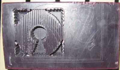
As already described above, Fablmodules was used to carve out the positive mold.
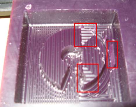
While the rough cutting went well, during the finish cut, the sticking tape got losened, effectively disturbing the process. The parts of the mold in red inset
faced the imapct and got a bit noisy. However, I have decided to go ahead with the noisy mold, as it seems it will create a small impact, may be a slope at the bottom (of negative mold). In the image besides, 2 distinct textures can be seen clearly, as an impact of inclomplete Finish Cut, over the completed Rough Cut. |
 |
At this moment (May 13, 2014 0015, IST) the mold is being settling down - Finally!
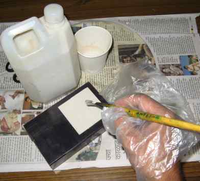
A local Molding Rubber (I am yet to get the name and chemical composition of this rubber) was procured, which is not Silicone Rubber. It is a commonly available,
low-cost rubber (approx. USD 5/lit). I initially, tried to pour it layer by layer. Meaning, put one layer using a brush, wait for it to dry out and then the next layer and so on. However, I realised, it is an extremely time consuming process and moreover, may not be required to be done this way. So after around 30 mins, I just poured in the rubber to fill up the mold. Pouring was done in such a way (a slow process) that the air bubbles were made to come up to the top from bottom. And then I removed the bubbles, all at once, while they were at the top. Now, waiting for the mold to take place.. |
|
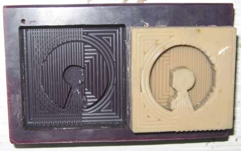
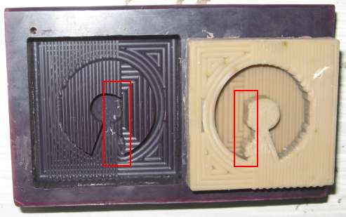
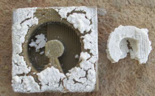
The images besides are that of the same object. The top shows the mold as it
is at this moment (May 19, 2014 2052) and the other one is just the same with marked areas to show the distortion. The top image clearly shows that the "Finish" cut was not completed (already described about this above). The half Rough Cut and the Half Finish Cut are clearly visible. Size of the output mold: 6.9 x 6.8 x 1.3 The second image shows the errors that were there in the positive mold, and which have been carried forward to the negative mold. I kept had poured in the material on May 13th and took out the mold without any efforts on May 19, 2014. Ofcourse, it had dried up completely by May 18, 2014. However, I kept it lingering for a day more. |
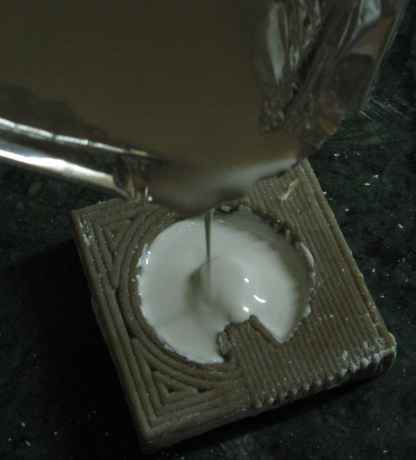
| Casting with Plaster of Paris, available locally. Note* In Pune, it costs for around Rs. 15/- per Kilo, as of May 24, 2014. ...yet to add... |
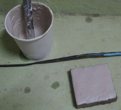
| Plaster of Paris poured onto the mold. ...yet to add... |
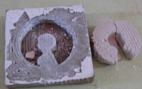
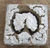
| A Broken cast of Plaster of Paris. ...yet to add... |
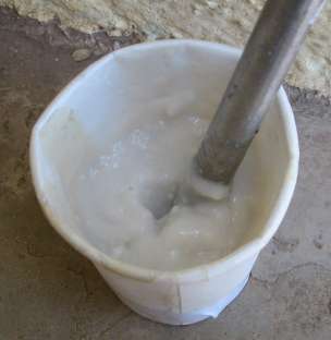
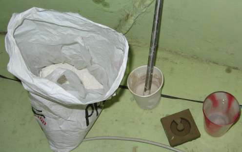
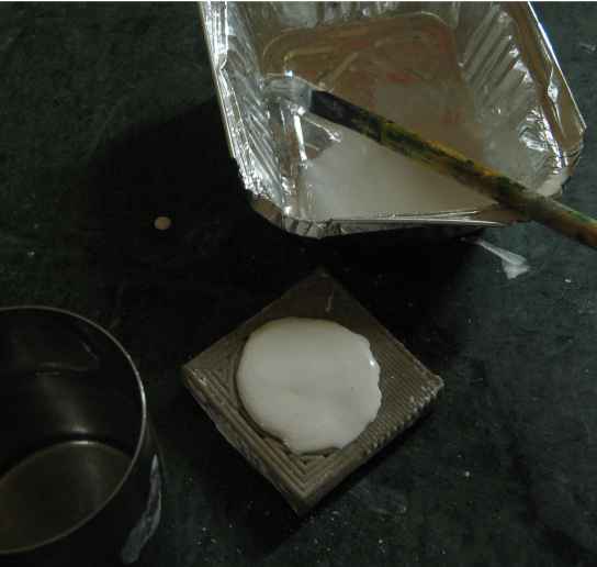
| Making of Instamold solution with 1 Part Instamold and
1 Part Water. ...yet to add... |
| Instamold poured on to the Mold, as of May 24, 2014 1309. ...yet to add... |
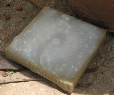
| Cast Object using Instamold ...yet to add... |
| Cast Object using Instamold ...yet to add... |
At this point in time, I had lost my heart... Pradnya, another friend at Fabacademy, surprised me with something!! -
| Pradnya Casted this object using Hydrostone, as a surprise gift to me!
This worked like a charm for me, to recast the same way. Thanking Pradnya would be out of spirit... however, what she has done is more than
just an elevation. |
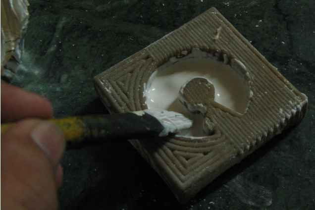
| Cast Object using Hydrostone Here, a retrial using Hydrostone is being realised. Pradnya's sharings helped me a lot to think of Hydrostone, afresh, as I had almost given up on this assignment. So, here in the image besides, I tried to pour in the Hydrostone mixed with Waterm using a brush, to avoid any air bubbles. |
| Cast Object using Hydrostone The Hydrostone mixed with water was then poured to achieve the state shown below. |
| Cast Object using Hydrostone Waiting for the case .. (as of May 29, 2014) |