@ Class 10 – Input Devices

Assignment: measure something: add a sensor to a microcontroller board that you've designed and read it

Efforts here also refer to Class 6. Hence, the already modified version of original Echo_Hello_World_PCB, has been used to do trials here. Class 6 shows the first modified version.


To go ahead with this assignment, a Schematic was drawn up, in Eagle 6.5.0.

I preferred NOT creating a Project. Rather a schematic directly. Main reason was that I did not find any advantage, worth considerable, to have a project created. Instead opening the schematic directly saved steps.

Eagle, anyway, on its own keeps track of changes and keeps saving backup files time to time, which is very useful feature. I will populate my notes, very shortly, in order to describe how I created the Schematic and Board files.

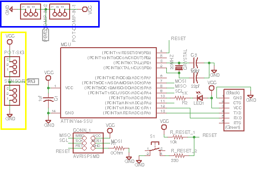
About the Functionality
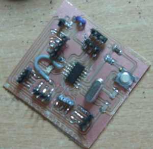
In the schematic, the blue box shows a voltage divider generating a "known voltage". The Yellow box is also a voltage divider, the output of which is changing based on a (resistive) sensor connected to it, as one of the resisotrs. More on this here(to create this page yet).

Let me describe a few related work-items...
1) The diagram besides shows 5 parts in the schematic. This is a very usefull technique of creating schematics, as the circuit size grows, resulting into increased complexity. I preferred, making parts of the schematic, to keep it is to see and understand. to Have this achieved, two different tracks that one wishes to join should be named same and eagle will ask whether one really wants to join the tracks. This allows the tracks to join but not show in the schematic. Key commands are "name" and "label"

2) W.r.t. the assignment, a reset switch has been added to the ckt. and a LED with limiting resistor too. Initially, I was hesitating to add a Reset Switch, as was not sure if that will fullfill the assignment. However, eventually, it was found to be falling in place, as a Reset Switch has its own timing requirements and is always a desired functionality.
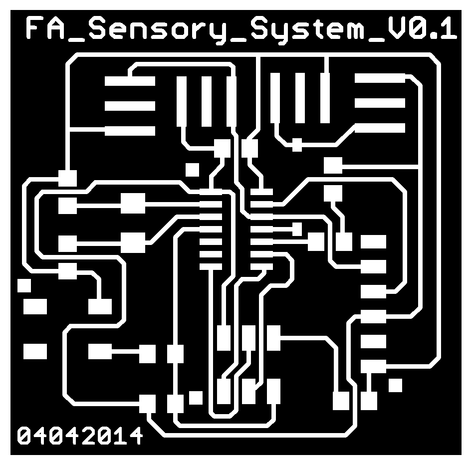
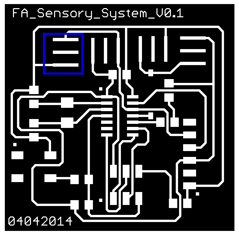

1) The file with blue box depicts the first attempt of the board file. Both the files are almost same except that the first board file has extra pads overlapped on the original SMD pin-heads.

2) This change helped to move ahead from issues in the first board (shown below).

3) Running DRC shows the overlap error. However, becasue it has been deliberately introduced, I approved the error and moved ahead.
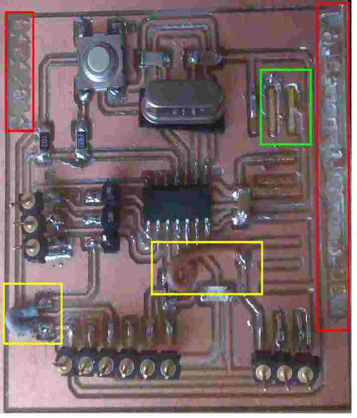


Issues with the PCB

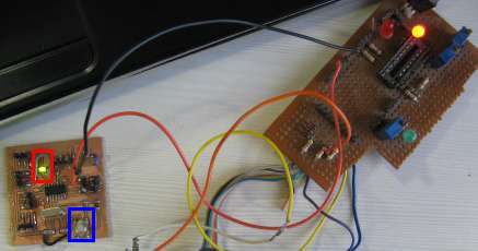
1) The green box shows that the track is stripped off.

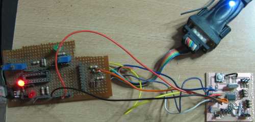
2) Yellow boxes depict the limitations during routing. These are jumper wires. A better routing is feasible and needs to be done. I could have used 0 Ohm resistors as jumpers, however, they were not available locally.

3) The red boxes show that the width of the text was not sufficient. The board file above has been corrected accordingly.

4) Post these errors, I have milled the new board, however component placement and putting some intelligence inside remains.


Post the issues (mainly, delicate connector pads) faced in first trial, I could come up with another board to resolve (same schematic, but modified board file).

Following changes were made to the original board design, using eagle 6.5.0.
1) Changed the width of the pads. To do this, I added recangular pads on top of existing connector pads, wherever appropriate.

2) Changed the size of charatcers that were not milled well in the first attempt.

note* - There are only a few modifications that can be done directly on board file, without a concern about the schematic file. Adding pads and texts are 2 of those. This means, there could be a few pads and characters on board file that may not exist on schematic and yet this is not a file-synch. error, as otherwise would be indicated by Eagle.

The image besides depicts the current limitations of routing that I did. There are 2 jumpers, which I could not resolve for. OFcourse, this is not too bad, as one can always reroute the board, from a previous stage or altogether afresh!

Programming the device - 1

Obvious that FabISP is available and needs to be used to program the MCU. However, that does not work for me...yet...

A working FabISP is yet to be achieved. So, I moved on to the hostoric serial programming method. DASA is one of the optios. avrdude supports DASA.

In this image
1) part of the general purpose board has the DASA implemented
2) the usb connector is a USB to COM converter that getss enlisted under /dev as ttyUSBx (OS: Ubuntu)
3) The square sized PCB is the target board.

Rest of the board is a primary development kit for ATTiny 2313 MCU... abondened now, but working..

Programming the device - 2
---In the abscence of FabISP---

avrdude is a commandline utility that can interface with various hardware programmers and send a program to a target AVR MCU. I used the following command to send program to ATTiny44 through DASA.

sudo avrdude -c dasa -P /dev/ttyUSB0 -p t44 -e -U flash:w:main.hex

The Image besides shows that all the three processed of avrdude are completed. It is to be noted that it took around 100 seconds to complete programming the MCU, as DASA is serial and too slow compared to a parallel porgrammer. For now, to try see the serial programmer works and the target board too, I have tried burning main.hex from FabISP's page.

Issues I faced
Initially, despite correct connections, the programming did not work. I was doubting my own understanding of MISO and MOSI. It seemed fine. Looking at the board, before checking the continuity, I realised that one of the tracks was stripped off, while I was removing the remains on the cut edges - It was the Ground connection! Once that was fixed with a jumper (black wire in the image above), everything worked.

knowing avrdude options
1) -c : programmer ID. For example - 'DASA', 'bsd, 'nibobee'
2) -p : part number. For example - t44, t2313, t45
3) -P : port. For example - /dev/ttyUSB0, /dev/tty0
4) -e : erase flash ROM
5) -U : .... This option performs memory operations.

Note* While the programming worked fine (meaning programmer and board are in action), a working program that uses the "input device", is yet to take place.

Programming the device - 3
---Blinking LED and functional Reset Switch---

The Image besides shows a working PCB, based on the process depicted above. The Red box shows a blinking LED and the Blue box shows a press switch that if pressed resets the MCU Board.
Note* The other General Purpose board contains the serial prograamer (DASA), as described earlier.

About LED Connections
Acc/to the schematic above, The LED has been connected over PA3 of ATTiny44. To have this LED turned on, one has to pull down the PA3 pin, as the Anode is permanantly connected to the VCC. R2 (which shown to be 1 KOhm, however the used value is 560 Ohm) is limiting resistor to save the LED from excessive Current.

This is where the programming would come in picutre.

About Source Code
The Description above drives the source code too. avrLED.c, avrLED.h are the source code files. And avrLED.hex is the output file to be uploaded to the device. Before going through the source code, let me describe what I had to do to build this code on Ubuntu 13.04

Setting up AVR-GCC on Ubuntu 13.04

sudo apt-get install gcc-avr

This command will install all the dependencies needed for developing and building firmware related AVR MCUs.

Generating the hex file to be uploaded to MCU

:generate .o file
avr-gcc -g -Os -mmcu=avr25 -D__AVR_ATtiny44__ -c avrLED.c

: generate .elf from .o
avr-gcc -g -mmcu=avr25 -D__AVR_ATtiny44__ -o avrLED.elf avrLED.o

: generate .hex from .elf
avr-objcopy -j .text -j .data -O ihex avrLED.elf avrLED.hex

After this the .hex file can be uploaded to the MCU, using avrdude, as described above. Note that the process above uses Serail Programmer (DASA) to program the MCU.

About Source Code

As described above the source code is simply about blinking a LED infinitely, with a known delay of 1 second.

Let me go line by line from the source code to share what I did.

Structure of the program
The whole program follows a certain structure.

1) avrLED.c file gets its definittions and include files from avrLED.h So, avrLEC.c includes only avrLED.h

2) entry point is main(). In that while() loop ensures the "infite event" of blinking. There is no exit from this while loop.

3) Acc/to the datasheet of ATtiny44 (also addressed as t44 henceforth), for a port-pin to be configured as output, it must be initialised to '1'.
(source: "If DDxn is written logic one, Pxn is configured as an output pin. If DDxn is written logic zero, Pxn is configured as an input pin").

4) As alreayd explined the Anode is always connected to Vcc, hence, the program logic demans that Kathode be Grounded in order to Turn ON the LED. And it be Not-Grounded in Order to allow LED experince no Potential Difference between Anode and Cathode, hence Not Turn ON.

This means, the corresponding Port Pin needs to be Pulled Down when LED is to be turned ON and be Pulled Up when the LED is to be turned OFF. If such ON and OFF is done repetitively, with a visible delay in between, the a blinking LED is at work!

PORT_LED ^= 1 << PIN_LED does the trick, wherein, ^ stands for bitwise xor and << means left shift.

About Fuse Bits

-U lfuse:w:0x62:m -U hfuse:w:0xdf:m -U efuse:w:0xff:m

...yet to add more on fuse bits - April 25, 2014

Cusotm Sensor (as input device)


background
In synchronisation with the "input device", I thought of creating a custom sensor. Based on previous discussios with farmers around, a humidity sensor based system, seems to be one of the needs, in order to predict upcoming diseases. There are many solutions to this, already available, however, a parallel thread of creating a sensor, using locally available material seemed another desired work. A sensor made up of available material, that too preferably close to nature would, perhaps, resolve for following situations -

1) A farmer herself/himself getting equipped with sensors, in case of deteriorated sensors and/or maintenance etc. This ofcourse demands a sensor-calibration utility to be provided to the farmer.
2) A biodegradable sensor would help, once we start caring about disposal of ruptured sensors.
3) If such a sensor can really be achieved then it will break the monopoly and unethical business tactics.

wayout
Sago (known as Sabudana in India) is a starch manufactured from extract of cassava (tapioca root). This food-item has its own property of soaking water. It also reacts to changes in humidify to a certain extent. I am trying to make a sensor out of this.

1) 3 tea-spoon sago was kept in a cup filled with water.
2) Paste was made out of it, after mixing the wet Sago.
3) The paste is kept for drying, not directly under the sun.

This trial produced a block of paste that had grown up black fungus, as it did not dry in time. Ofcourse, I could have taken care for that which I will do now.

Moving on to another trial, with better attention and responsibility...

Home