Embedded Programing
I designed a board derived from the basic hello LED board. I added a button and an additional 2x2 pin connection. The 2x2 is used for networking with an input board I made for networking later in the class. I used the Arduino AVR app to program my altered hello RGB LED board.
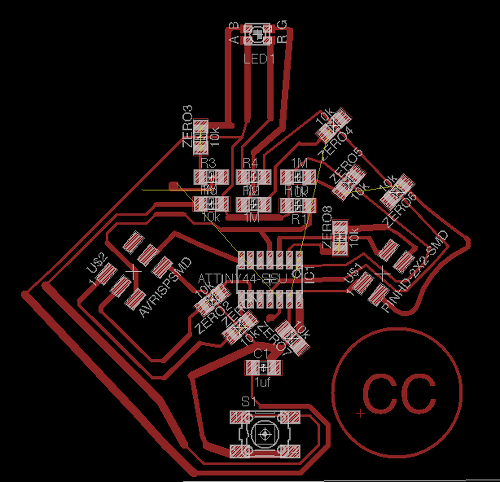
I designed this board in Eagle. All the components are the same as are on the hello RGB LED board with the exception of the 2x2 traces, the button and some zero ohm resistor bridges. Because I ran out of zero ohm resistors, I used copper wires to improvise bridges.
To program the board I used the Arduino app. To set up the program to upload my code, I needed to tell the software what microcontroller I was using. To do this, I went to the Tools column > Board > ATTiny44 8Mhz. Then I went to Programmer (also found under Tools column) > AVR Dude MKII for the model of programmer I was using.
Francisco helped me with writing the code. He explained to me how the software works and the logic behind the coding.
const int ledR = 2;
const int ledB = 1;
const int ledG = 0;
const int button = 8;
const int servo = 7;
int mode;
// the setup routine runs once when you power the board:
void setup() {
// initialize the digital pins
pinMode(ledR, OUTPUT);
pinMode(ledB, OUTPUT);
pinMode(ledG, OUTPUT);
pinMode(button, INPUT);
pinMode(servo, OUTPUT);
digitalWrite(ledR, LOW);
digitalWrite(ledB, LOW);
digitalWrite(ledG, LOW);
mode=0;
}
// the loop routine runs over and over again forever:
void loop() {
if (digitalRead(button) == HIGH) {mode=mode+1;}
if (mode=7) {mode=0;}
if (mode=0) {
digitalWrite(ledB, LOW);
digitalWrite(ledR, LOW);
digitalWrite(ledG, LOW);
}
if (mode=1) {
digitalWrite(ledB, HIGH);
digitalWrite(ledR, LOW);
digitalWrite(ledG, HIGH);
}
if (mode=2) {
digitalWrite(ledB, LOW);
digitalWrite(ledR, LOW);
digitalWrite(ledG, HIGH);
}
if (mode=3) {
digitalWrite(ledB, LOW);
digitalWrite(ledR, HIGH);
digitalWrite(ledG, LOW);
}
if (mode=4) {
digitalWrite(ledB, HIGH);
digitalWrite(ledR, HIGH);
digitalWrite(ledG, HIGH);
}
if (mode=5) {
analogWrite(servo,168);
}
if (mode=6) {
analogWrite(servo,196);
}
}
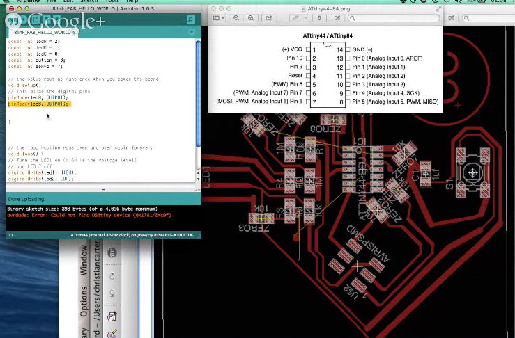
A screenshot of the Arduino app programing the boardvia the AVR Dude.
The code is broken up into pin assignments for outputs or inputs and commands for those pins. The top portion of the code designates what pins are. The lower more detailed section designates modes and what each mode does. I have it programmed to cycle through each primary color with a button push. The fifth mode moves the servo controlled lens for focusing in one direction and the sixth mode reverses it. Pressing the button again will turn the system off.