Output devices (Apr 17)
Assignment
Add an output device to a microcontroller board and program it to do something
This week I decided to try DC motors and these experiences are a first introduction to design the motor control board for my final project. To regulate the power of the DC motors, use a technique called duty cycle or PWM duty cycle. Juan Ranera and I are going to use the control of DC motors in our final projects. For this reason, we decided to share the experiences of this week and we have investigated together.
Duty Cycle
A duty cycle is the percent of time that an entity spends in an active state as a fraction of the total time under consideration.The term is often used pertaining to electrical devices, e.g., switching power supplies.
A better way of doing speed control is to switch the power to the motor on and off very quickly. The speed of a motor is proportional to the average voltage supplied across it, so if you switch the voltage on and off quickly enough, the motor only "sees" the average voltage. Because of the weight of the motor armature and its inertia, the motor speed won't vary noticeable between each on and off pulse, provided the pulses are short enough and close enough together.
In a periodic event, duty cycle is the ratio of the duration of the event to the total period of a signal.
where
is the duration that the function is active.
is the period of the function.
The devices normally used to switch the power "on" and "off" are Metal Oxide Semiconductor Field Effect Transistors or MOSFETs. These devices are used because the can switch very large currents under the control of a low signal level voltage.
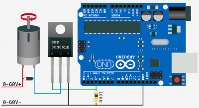
PWM motor DC control
This circuit is pretty simple. Is possible control the speed of the motor, but only in one rotation direction.
The only part that looks funny is the resistor. This is a pull-down resistor. The resistor holds the gate low when the arduino does not send a high signal. This is here incase the arduino comes loose, or the wiring is bad it will default to off. You don’t want this pin to ever be floating as it will trigger on and off.
The parallel diode is a proteccion. Any time you are powering a device with a coil, such as a relay, solenoid, or motor, you need this guy, and don’t leave home without it. What happens is when you stop powering the coil, a reverse voltage, up to several hundred volts, spikes back. This only lasts a few microseconds, but it is enough to kill our MOSFET. So this diode (only allows current to pass one way) is normally facing the wrong direction and does nothing. But when that voltage spikes comes flowing the opposite direction, the diode allows it to flow back to the coil and not the transistor. We will need a diode fast enough to react to the kickback, and strong enough to take the load. A rectifier diode like the 1N4001 or SB560 should do the job.
If you are looking for extra protection you could use an optoisolator between the Arduino and the transistor. An optoisolator optically isolates both sides (high and low power) of the circuit so the high-voltage can not possibly come back to the microcontroller.
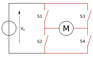
H Bridge
If you want to control the speed and the two directions of rotation of the motor, use a configuration H bridge. An H bridge is an electronic circuit that enables a voltage to be applied across a load in either direction. These circuits are often used in robotics and other applications to allow DC motors to run forwards and backwards. H bridges are available as integrated circuits, or can be built from discrete components.
Using the nomenclature above, the switches S1 and S2 should never be closed at the same time, as this would cause a short circuit on the input voltage source. The same applies to the switches S3 and S4. This condition is known as shoot-through.
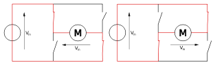
H bridge theory of operation
The H-bridge arrangement is generally used to reverse the polarity of the motor, but can also be used to 'brake' the motor, where the motor comes to a sudden stop, as the motor's terminals are shorted, or to let the motor 'free run' to a stop, as the motor is effectively disconnected from the circuit. The following table summarises operation, with S1-S4 corresponding to the diagram above.
S1 S2 S3 S4 Result 1 0 0 1 Motor moves right 0 1 1 0 Motor moves left 0 0 0 0 Motor free runs 0 1 0 1 Motor brakes 1 0 1 0 Motor brakes 1 1 0 0 Shoot-through 0 0 1 1 Shoot-through 1 1 1 1 Shoot-through