Electronics production (Feb 13)
Assignment
Make the FabISP in-circuit programmer
David Andy Valentin
hello.ISP.44.cad board components traces interior
hello.ISP.44.res.cad board traces interior
inventory microcontroller crystal USB connector ribbon connector Zener diode jumper
firmware.zip
USB power
make clean
make hex (sudo)
make fuse (check programmer in Makefile, may need to repeat)
(sudo) make program desolder SJ1 and SJ2 make IDC ISP cable, connecting header pin 1 to pin 1
This week we have fabricated the first PCB board whith the Roland Modela. I decided to use the design of David A. Mellis. I had never made a printed circuit board with a milling machine. This board use a small microcontroller, the ATinny44 and it can be programmed with the Arduino software.
The first thing I have done is to follow the tutorial of David.
David A. Mellis description with some extra links
The FabISP is an in-system programmer for AVR microcontrollers, designed for production within a FabLab. That is, it allows you to program the microcontrollers on other boards you make, using nothing but a USB cable and 6-pin IDC to 6-pin IDC cable. It's based on the USBtiny and V-USB firmwares, which allow the ATtiny44 to perform USB communication in software. Programming can be done through avrdude. The schematic (PDF) is super simple: USB connector, ATtiny44, and 6-pin ISP header, with assorted passive components. I started with the Eagle files for the USBtinyISP, although there's almost nothing left of it. Most of the parts for the FabISP are in the FabLab inventory. Exceptions include the Mini-B USB connector (SparkFun, Digi-Key), 12 MHz crystal (Digi-Key), and 18 pF capacitors for the crystal (Digi-Key).Datasheet ATtiny44.pdf
To make the FabISP, firstly I installed the fab modules and dependencies.
How to install fablab modules in Ubuntu.
- To install it, unzip fab_src.zip and cd to the folder it's in.
- Run in a terminal
- make file
- make install #if you have any problem try: sudo make install
- fab
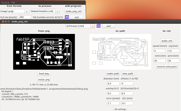
Steps to run de fablab modules
- from format = image(.png)
- to process = Roland Modela (.rml)
- click make_pnkg_rml
- loand.png -> to select the file.png
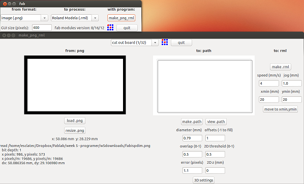
- default = mill traces 1/64 if fabisp.png or 1/32 if fabispdim.png
- click make .path
- Select Xmin,Ymin to set the "zero" XY in your board and click move to xmin,ymin
- click make .rml,appear new icon to send it, click it
You can change the 3D settings if you have any problem to make correctly the PCB
Fabrication
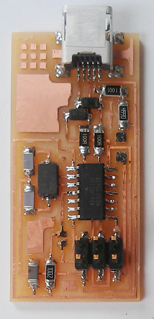
I used the David A. Mellis PCB to make the board, but I changed the crystal oscillator 12Mhz for 20Mhz and capacitors C2,C4 of 18pf for 10pf. In the Roland Modela change the different tools 1/64 or 1/32.
Must be careful with the right direction of the ATTINY44 and the diodes, the rest no matter the direction. The Attiny44 have a point to indicate the number pin 1 and the diode has a line to indicate the catode.
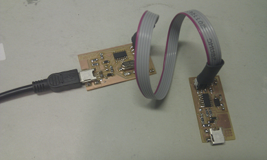
Hardware Interface
The board connects to the computer using a Mini USB cable. It connects to the target (the board being programmed) with an 6-pin cable on the 2x3 ISP header.
Programming
Download the firmware.zip file above and unzip it. You can edit Makefile the most important settings, for example:
Select crystal oscilator
If the Crystal oscilator is 20Mhz
#F_CPU = 12000000 # edit this line for crystal speed, in Hz
F_CPU = 20000000 # edit this line for crystal speed, in HzIf the Crystal oscilator is 12Mhz
F_CPU = 12000000 # edit this line for crystal speed, in Hz
#F_CPU = 20000000 # edit this line for crystal speed, in Hz
Select the programmer
This symbol # comment line and will not run.
FabISP to program your FabISP
AVRDUDE = avrdude -c usbtiny -p $(DEVICE) # edit this line for your programmer
#AVRDUDE = avrdude -c avrisp2 -P usb -p $(DEVICE) # edit this line for your programmer
Avrisp2 to program your FabISP
#AVRDUDE = avrdude -c usbtiny -p $(DEVICE) # edit this line for your programmer
AVRDUDE = avrdude -c avrisp2 -P usb -p $(DEVICE) # edit this line for your programmer
Steps to program the Atinny
- Solder SJ1 and SJ2
- Power the board (using a USB port, or USB charger)
- Using a standard programming cable, connect your programmer to be to another programmer (connect Pin 1 to Pin 1, Pin 2 to 2 and so on)
- if you need to edit the Makefile to make a change, do it
- Program it with another programmer
- make clean
- make hex
- make fuse
- make program
- Unplug the programming cable, remove power, and desolder the jumper
- You can connect the FabISP to the PC or Laptop to view if detect it.
- Linux command: lsusb
Bus 003 Device 004: ID 1781:0c9f Multiple Vendors USBtiny
- Windows in device manager


- I programmed more programmers successfully.
We had some problems with USB ports when programming some programmers. In this case we have changed USB port and has solved the problem. In Windows does not have detected these problems. Still i do not know wich it is the problem, but it could be some hardware incompatibility.