Electronics design (Feb 27)
Assignment
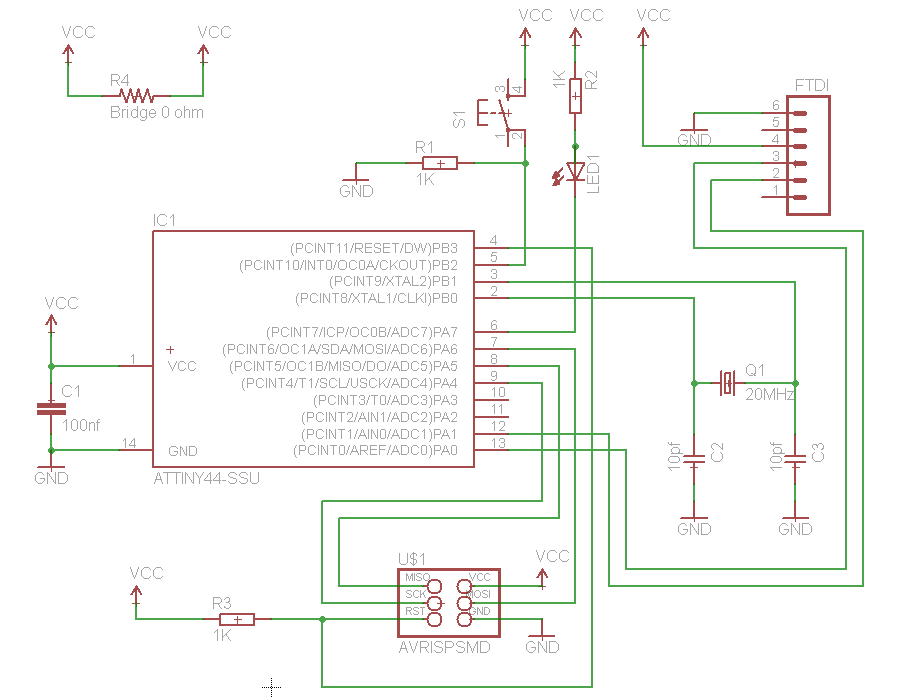
Redraw the echo
hello-world board, add (at least) a button
and LED
(with current-limiting resistor), check the design rules, and make
it
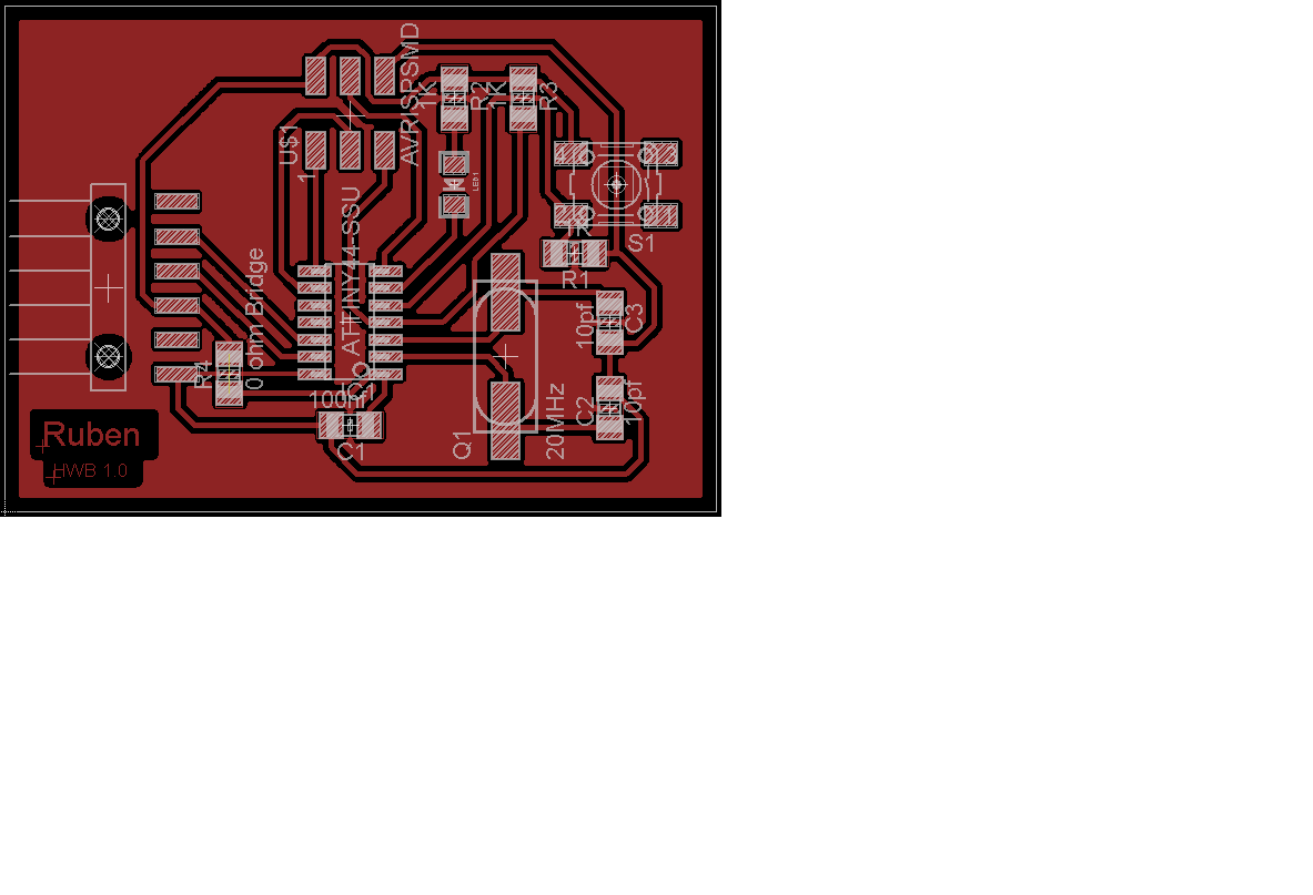
For design of the PCB,
I used the Eagle
software. This is a simple software and easy to learn. To
install it,Choose "Run as Freeware" on first run.
Luciano sent us a Fablab
library for Eagle, but the FTDI connectors I did not
found. I found them in the SparkFun
eagle library , specifically Sparkfun-Connectors.lbr
I added the FTDI connector to the Fab Hello.lbr and
I changed the name to Fab RHello.lbr .
To install, copy these files in your folder \Eagle\lbr
http://www.cadsoftusa.com/download-eagle/
- Use the Fab RHello.lbr to add the components
- Connect components with Net don't Wire
- Microcontrollers note:
- You use a decoupling capacitor between VCC and GND
near of the microcontroller, in general 100nF.
- The micontroler IO ports usually are able to absorb
more current than it can be supplied. Connect the LEDs
to VCC instead of to GND and turn on by 0. LEDs have
polarity be careful.
- When reading a microcontroler port, make sure the
cable is not in the air, you can use pull-up
or pulldown resistors to force states reading.Some
microcontrollers have them internally and are
configurable
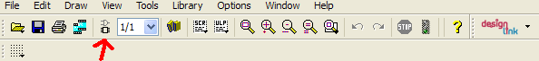
- When you finish the schematic, click in Board to
generate the PCB with this schematic.
- If you have crossing tracks, you can use resistors 0 ohm
as a bridge.
- You can generate new components after, remember click in
Board to refresh it.
- The correct position of the components makes easier our
job later. Check the correct position to minimize the
distance between pins.
- Then use the icon Route
 to create tracks.Use 45 degrees to route, never 90.
Electrons move along a track like water through a pipe.
to create tracks.Use 45 degrees to route, never 90.
Electrons move along a track like water through a pipe.
- You can undo a track routed by pressing RipUp.

- Configure Eagle for black background. This is useful for
creating the PNG image to the Modela. "Options -> User
Interface" Layout/Bacground select black
- To generate the ground plane use a polygon
 never
a rectangle. Select these icons with 0.016 Isolate and
0.016 spacing
never
a rectangle. Select these icons with 0.016 Isolate and
0.016 spacing

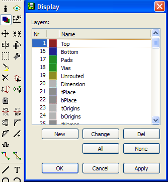
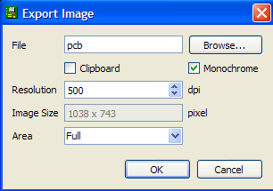
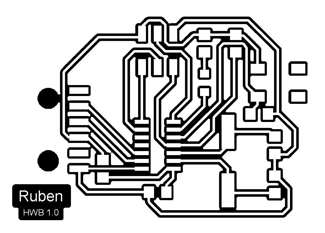
- To create the PNG image, you select Display icon first,
and choose None and after only Top. Then go to File ->
Expot -> Image ( select Monocrome and 500dpi )
Files of R hello world board
r
hello world board.sch
r hello
world board.brd
r hello
world board.png
cut
r hello world board.png
 Schematic Schematic
|
 PCB PCB
|
 Cut png Cut png
|
 PCB png PCB png
|
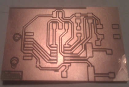 PCB fabrication PCB fabrication
|
|