Fab Lab Barcelona SuperNode /Fab Lab Sevilla /Jose Perez de Lama
Week 14 / networking and communications / 24.04.2013
[assigment]
Build a wired &/or wireless network with at least two nodes.
Class syllabus::
http://academy.cba.mit.edu/classes/networking_communications/index.html
[assignment development]
This week i went for the hello.bus basic assignment as suggested in the class. It consists in making several PCBs that are connected with a serial bus, assiging to each of them a different node number-Id, and being able to address each of them.
After all these weeks we have become quite proficient, and PCBs are coming out quite fluently...
I downloaded the board files from the class page:
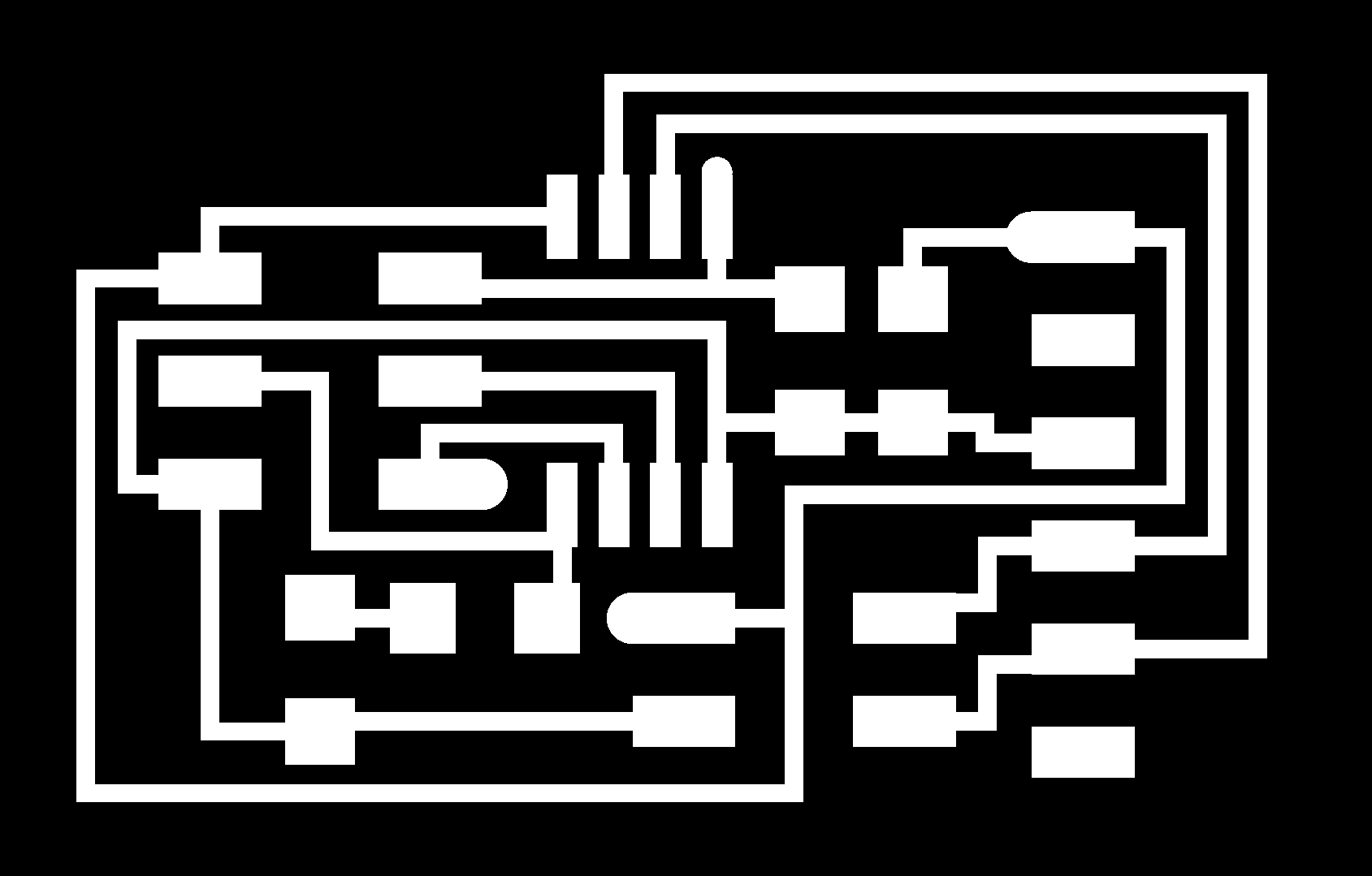
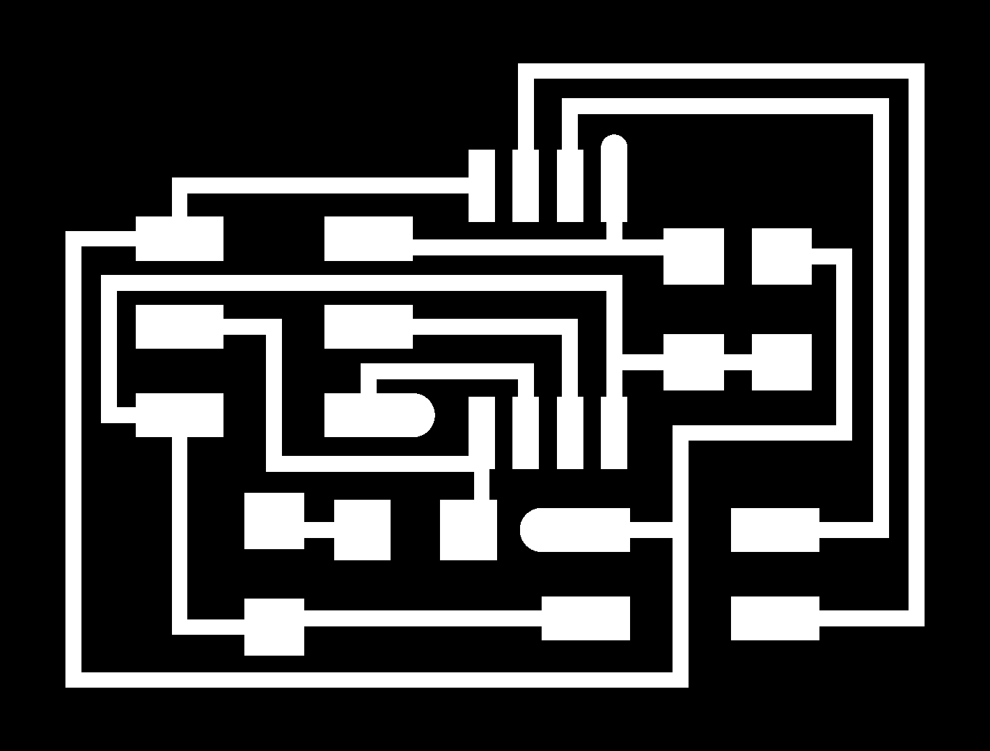
hello.bus.45.bridge.cad board traces
hello.bus.45.node.cad board traces
hello.bus.45.c makefile

hello.bus.45.node.png

hello.bus.45.bridge.png
[milling and stuffing]
Then i milled the boards in the iModela, following the workflow that we have established in the former class:
Png > fabmodules > dxf > Rhino (tweeking the width of the narrower sections and adding label) > .ai > iCreator > iController
Parameters::
Fab Modules:
diameter = 0.4mm
offsets = 6
Overlap = 0.5
Pixel error = 0.8
iCreator:
Engraving mode
depth = 0.01 mm [almost new mill]
speed = 40 mm/min
Tool: 45º 0.2mm tip mill
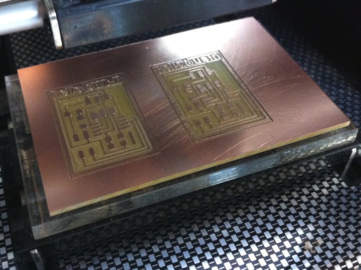
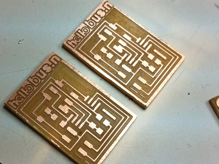
The first two boards [nodes] were milled in one hour and ten minutes each, with only one layer of 0.01 mm.
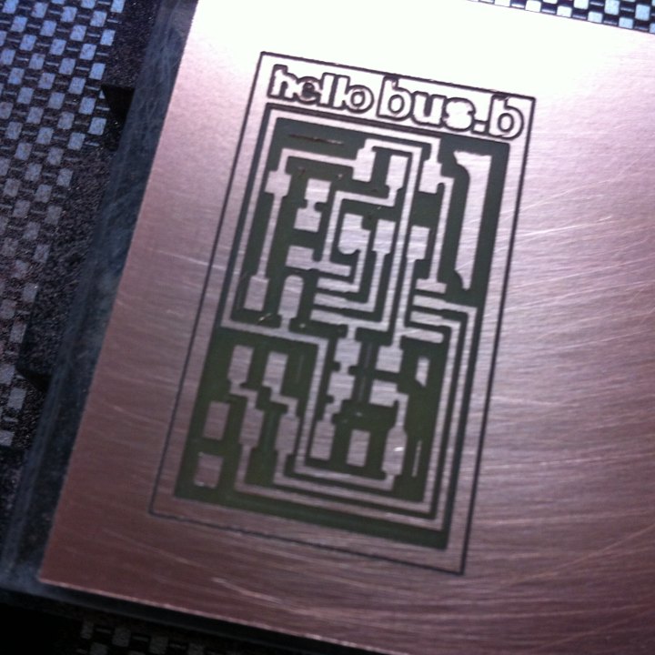
The third board [bridge] needed two milling layers [0.02 = 2*0.01mm]. It took more than two hours to mill. Either, i didn't physically sero the mill with enough precission or the mill wasn't sharp enough any more and the cutting was less efficient.
The reuslt of the boards from the milling point of view is high quality. Before milling i srubbed the FR1 board with soap and water. After milling i srubbed it again and sprayed it with lacquer.
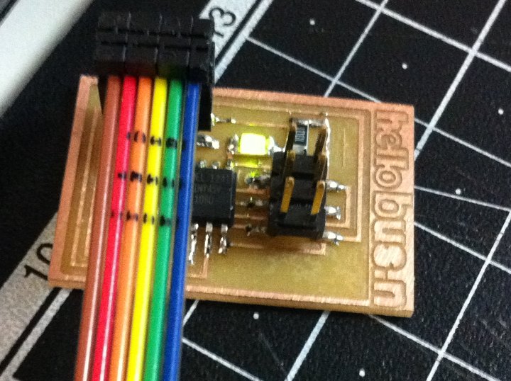
Then we stuffed the board. Last week i gave myself for my birthday a Weller 15W soldering iron, and i was using it. Even if the tip is not as fine as our other favourite soldering iron, it feels, to me, easier to use.
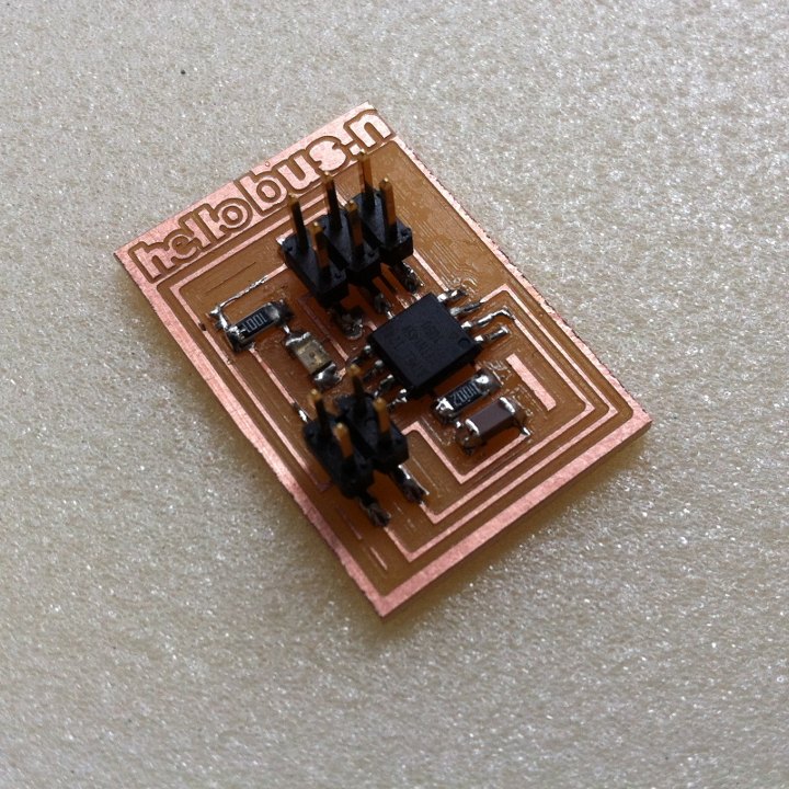
The picture may not look that good, but the node board worked right away without any need to debug!
[bootloading and testing]
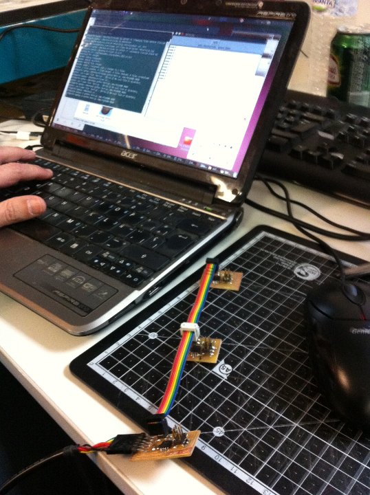
We connected 1/ the four pin cable from the hello.board to the USB computer port using a small hack by Buzon that enabled us to use the FTDI cable, as can be seen in the picture, 2/ the ISP port of the board to the AvrispII programmer, and 3/ the AvrispII to another USB computer port: green light!
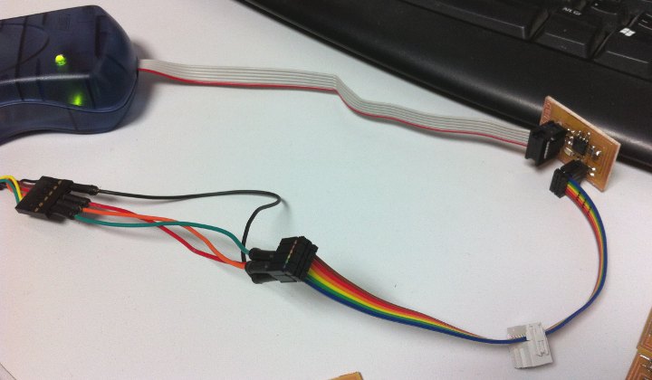
Then i followed Anna Kaziunas tutorial, which worked right away. In fact, my colleagues had spent some time before, and i joined them just when they were getting the little network to function. Afterwards it was easy form me to follow their instructions.
Even if i had milled three boards, i programmed one of the hello.bus.node boards, to incorporate it to the (linear) network my colleagues had made.
I modified the modified C make file provided in Anna K's tutorial, using the linked modified make file [zip file], and changing the line were the node Id is set, setting it to "3". We already had nodes "0", "1" and "2" functioning all right in our little network.
#define node_id '3'
I compiled the modified file in Jose Buzon's Windows machine, as i still have some issues with my own avr-gcc on Ubuntu 10:make -f hello.bus.45.make
Next, typing in the terminal (no sudo in Windows; in Ubuntu it would need sudo):
sudo make -f hello.bus.45.make program-avrisp2
i bootloaded my hello.bus.node.45 board as node '3'.
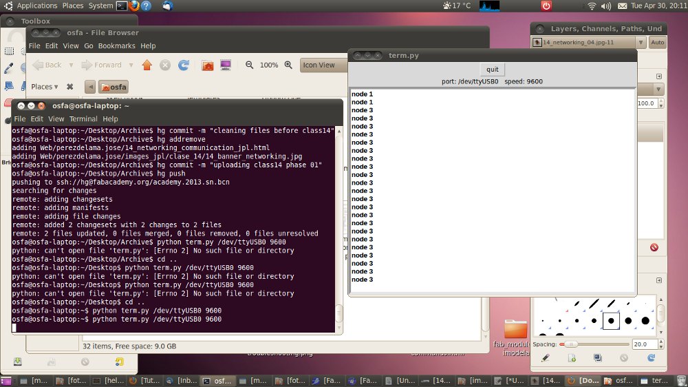
Then i moved back to my Linux-Ubuntu-10 machine and i downloaded term.py, the little python script to test the networked boards. I put it in my home folder and typed in the terminal:
python term.py /dev/ttyUSB0 9600
[/dev/ttyUSB0, for the port direction; and 9600 for the baud rate of the computer-to-board serial communication], to open the term.py interface.
Here, pressing the number 0 key, the LEDs in all boards shine once, and the LED in board 0, the bridge shines twice. "node 1" appears in the term.py terminal. When typing 1, the LED in node 1 shines twice; node 1 appears in the termy.py terminal; when typing 3 the LED in board three shines twice; node 3 appears in the term.py terminal. In the configuration i wa susing i was lacking node 2, - we had a very short cable... When typing 2, the missing node, all of the board LEDs shine once, but there is no prompt in the term.py terminal. And this completes the proposed assignment.
I hope that using this system, we will be able in the machine project and in the final project to connect input and output devices... We will see...
///
Unless otherwise stated, information in this page is downloadable under a Creative Commons Attribution-Share A Like license; attribution: Jose Perez de Lama / Fab Lab Sevilla / Fab Academy 2013. This work is fully based in the documentation provided by Neil Gershenfeld / Fab Academy 2013; and Anna Kaziunas, AS220 Fab Academy 2013.

previous class:: 13 output devices / next class:: 15 mechanical, machine design
return home /perezdelama.jose