Fab Lab Barcelona SuperNode /Fab Lab Sevilla /Jose Perez de Lama
Week 05 /20.02.2013 /3D scanning and printing
[assignment]
3D scan and object [extra credit: make the scanner]. Design and 3D print an object; small, few cm [extra credit edit and print and object that you scanned].
Link to class syllabus & tutorial:
http://academy.cba.mit.edu/classes/scanning_printing/index.html
[preliminary comments]
The Fab Academy's rythm has become intense. If you loose concentration for a couple of days, you become definitely behind. This has happened to me, because i got diverted by trying to make the iModela work with Fab Modules. I learned a lot, based upon some beta files sent by Barcelona, that i had to tweak a bit. I learned about finding and setting ports in Ubuntu and Cups, and RML-1 language, and the Fab Modules data-flow: png_path, path_rml, fab_send... Now we can move the iModela's tip wherever we want, and we can send it rml [path] files with the right coordinate-dimensiones, but we still cannot place the 0,0,0 right - the rml_move.rml & imodela_move.imodela files. I guess we might need to move to PR - relative coordinates -; but i had to finish the 5th class assignment, or rather to begin it, and i decided to park it for some days... We still can do it with the iModela's own software and Windows... But of course, that isn't so exciting :).
[assignment development]
We had had some small experience scanning using 123D_Catch and Kinect+Firefly+Grasshopper, that we learned from Jens Dyvik in one of his visits to Sevilla. But then... i realized i had to get something made fast and efficiently in order to get ready for the next exercise which again will be difficult for us. So i decided myself for 123D-Catch which seemed to be easier.
I started with the idea of scanning a body part; one of my fingers. I thought it was interesting this flow-interaction between a living element, digitazing it and turning it into a physical object again. Jose Buzon helped me take a couple-sets of pictures, and here are some of the results. They do look like some Francis Bacon picture, but we didn't get to far as the goal of the assignment is concerned. We tried to put a patterned background in order to try to help the software reconstruction process, and then as well drawing some patterns on my finger. However, it seems that one has to take more time, some patience, and a much better lighting. We were doing it night-time, with artificial lighting...
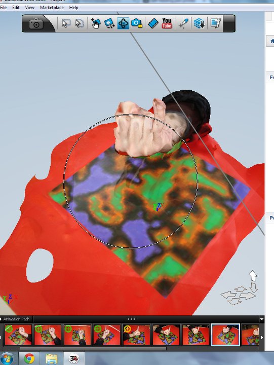
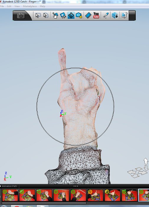
Figures 02, 03: One of the several failed tests scanning my small finger; 123D 3D model and mesh. I hope it doesn't look obscene or provocative, i just didn't know how to place the finger better to 3D scan it...
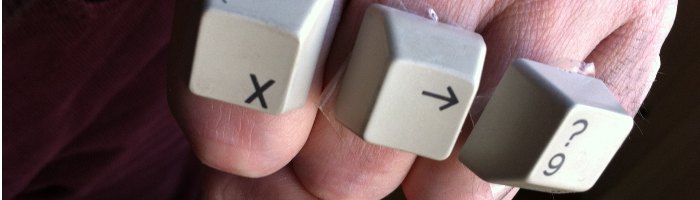
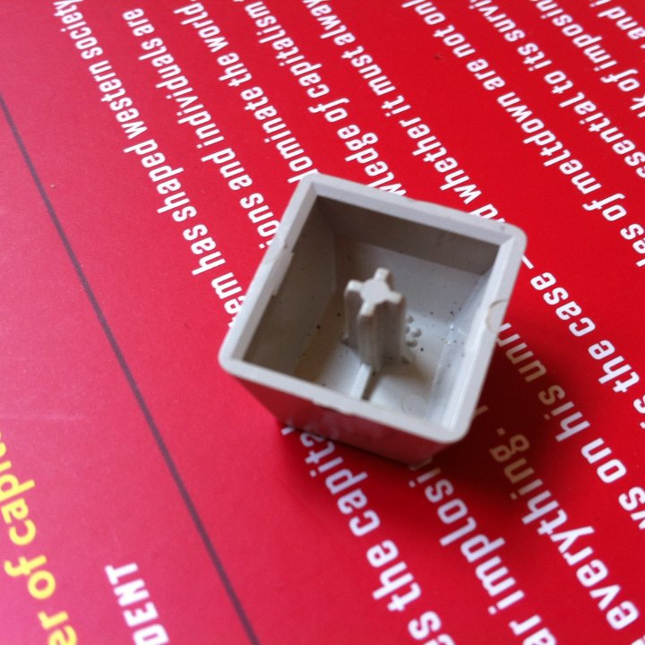
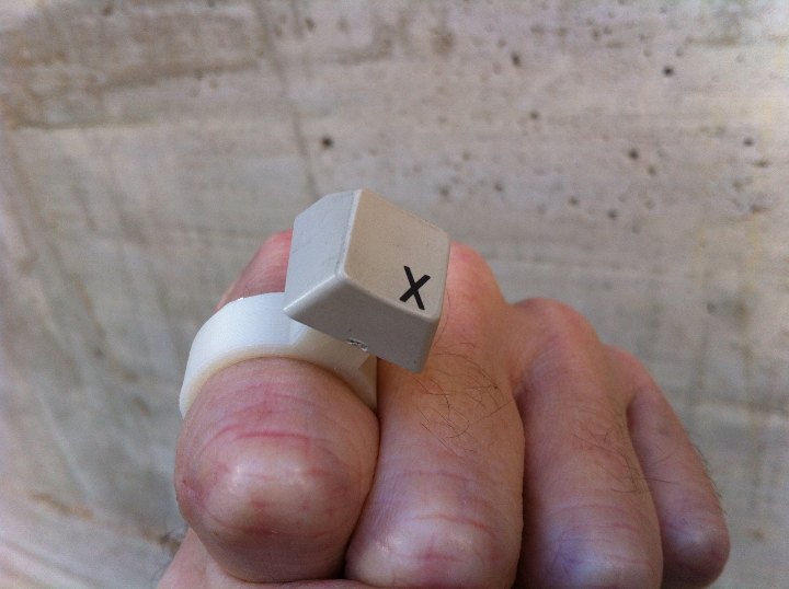
So, being by myself on the weekend, i realized taking pictures of my own finger was going to be kind of difficult, and i remembered an old mini-project, and decided to recover it. The project was to 3D print some rings where i could fit discarded keyboard-keys. Together several keys, in a rapster style, could make short messages, like for example "F-A-B". I didn't have these three letters "in stock", so, by now, i am using whatever i have, as in the upper picture.
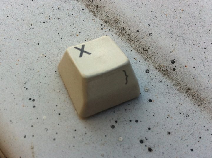
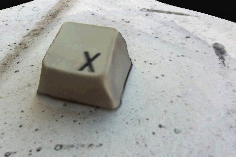
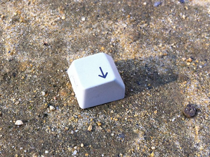
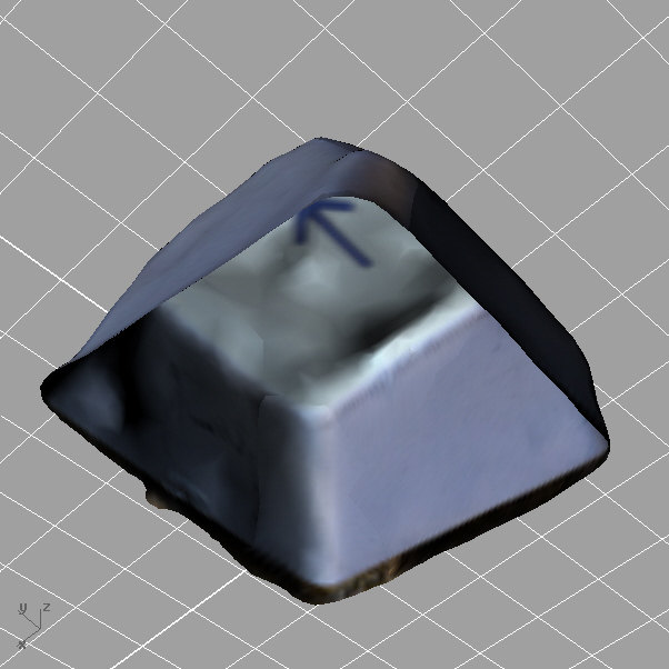
Figures 04, 05: Picture of keyboard-key and image of first 123DCatch scan test
This is a picture of one of the pieces i decided to scan, and a first try using the 123D Catch I-Phone App. Even it is very nice, the geometric quality is still poor. As it was already becoming dark, i switched to 3D parametric-modelling the ring that i was planning to print and use as support for for the key. The key already has an interesting design to fix to the original keyboard, that seems quite convenient to use for the ring design. I decided to try a tight cylindrical hole were the key's cross should press-fit.
The tool i used to design a parametric ring is Rhinoceros+Grasshopper. A ring design is actually very convenient to design parametrically so that it can be modified to different finger sizes. I had designed one ring before, but it wasn't parametric. So this felt like a good opportunity to turn it parametric, which of course is not so difficult. The parameters that i decided to use are in the following image. There are quite a few, so it should be easy to adapt it to future variations. I actually made two different definitions. One composed of two different pieces, that i think will be easy and rather accurate to 3D print with the Makerbot that we have for this assignment; and a second one that is not so nice, but that will be even easier to print, and which is made by a single piece.
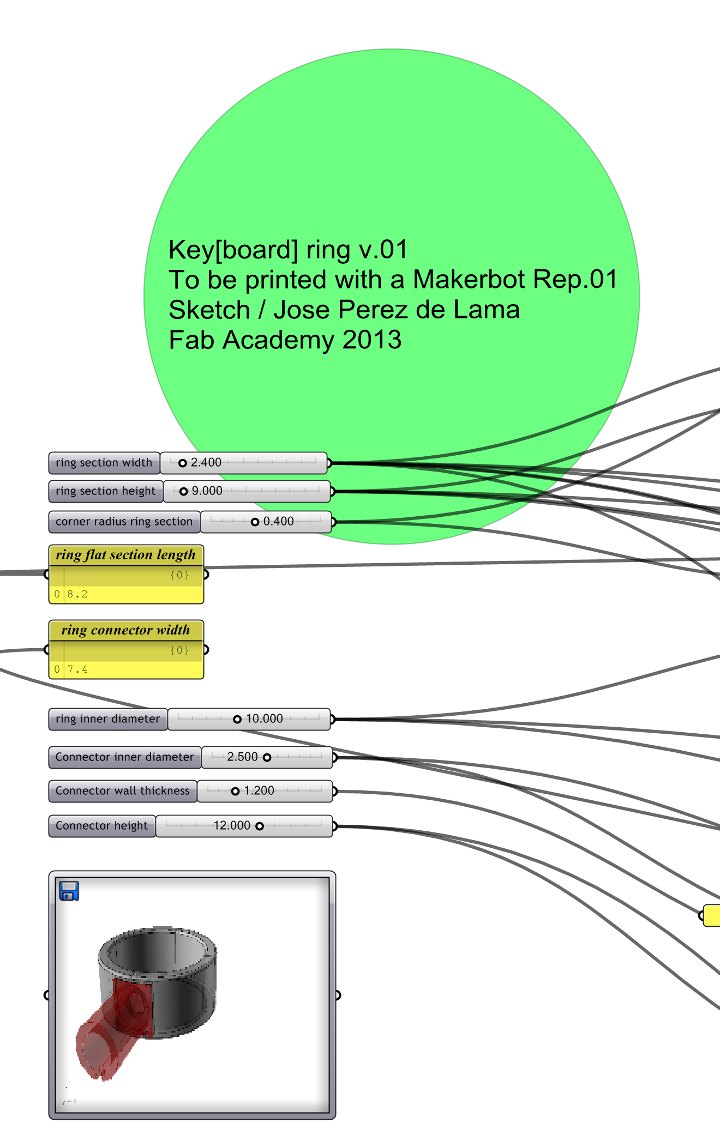
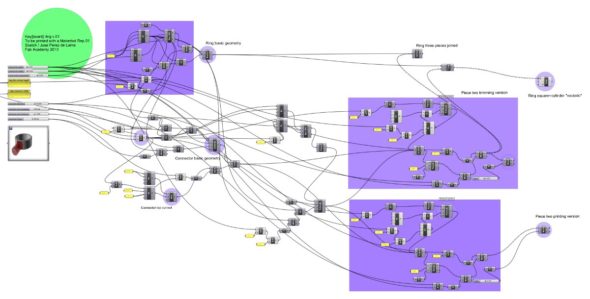
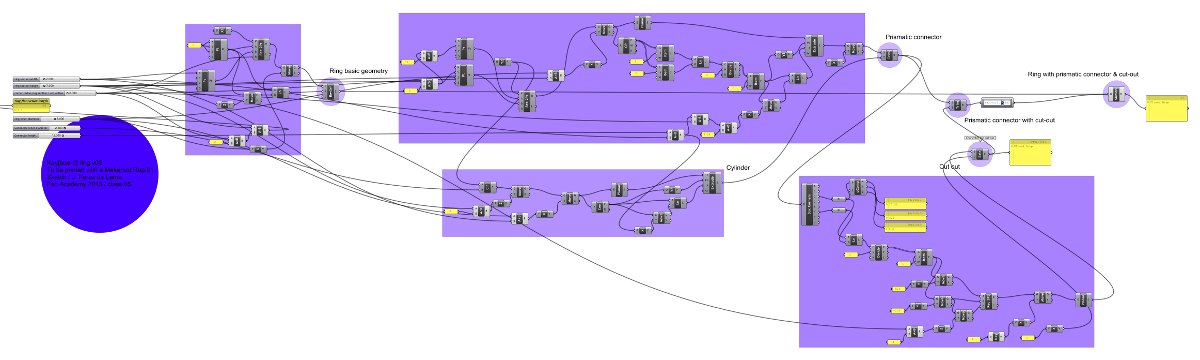
Figures 07, 08, 09: Grasshopper parametric definitions for two different ring designs. In the upper image, detail of the parameters available for the first design, including ring section height, width and corner chamfers; inner ring radius [it says diameter but it is actually radius] and connector inner diameter, wall thickness and height.
And this is how the two designs look like. The images are "baked" instances of the two designs; the last one being a view of the exported .stl files for the first version with the two component parts; the pieces should be ready to 3D print.
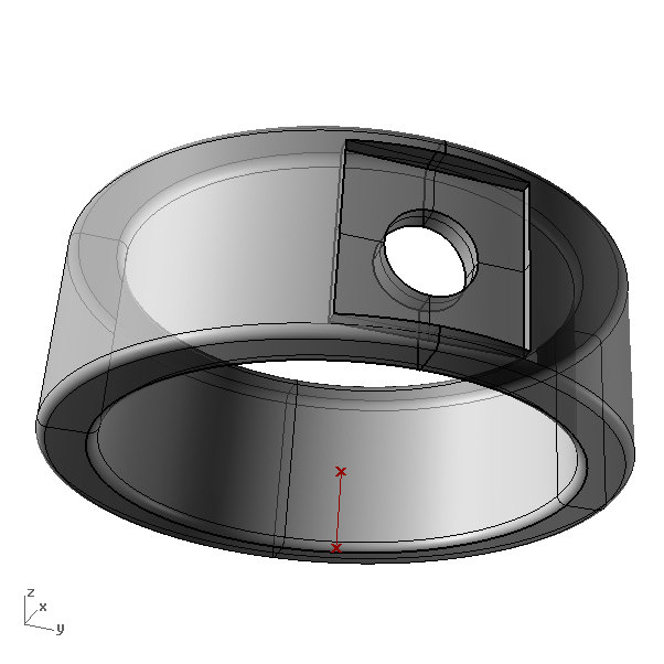
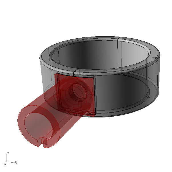
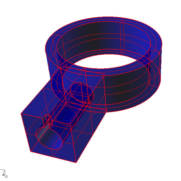
Figures 10-13: Rhinoceros / Grasshopper file captures; ring 01, ring 02 and ring 01 .stl files.
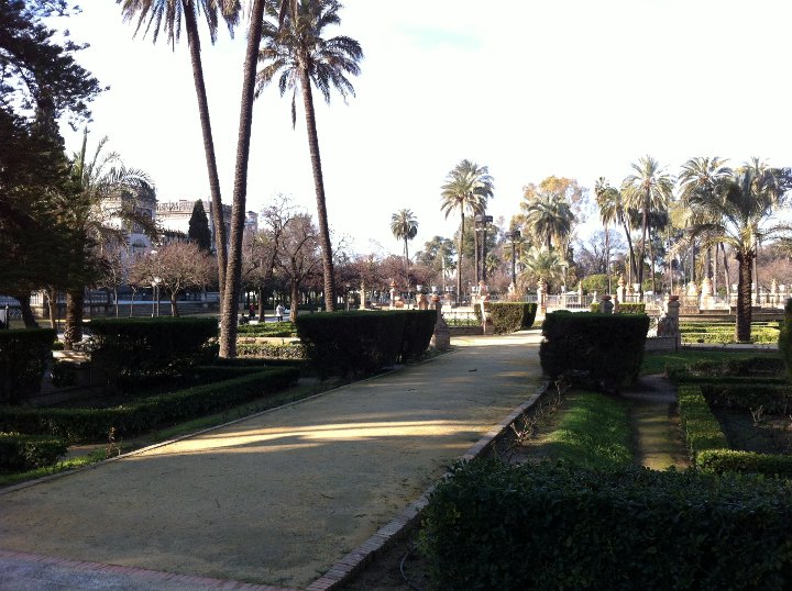
Next day, Sunday, then, thinking it would be better to have good outdoors light, i took a walk in the park close to home, Parque de María Luisa [in the picture, so that you can see, because it is quite beatiful] to take a good set of pictures of the key.
Back home, i updated an old XP Windows including antivirus, and downloaded 123DCatch to see if this would give me a better interface than the cell-phone. Actually in the first test with Jose Buzon in the Fab Lab, we had been retouching 123DCatch initial proposals "teaching" the system some points, and it obviously seems that this is the way to go... However, i just went, as a first one-week test for the 3D model generated in the cloud. Even if it is not geometrically very tight, it is visually quite nice; it does have a cool cyberpunk flavour. I Thinks that 123DCatch, as it is right now, is very good for videogame designers, because it achieves a very good visual quality. But probably it is not so good yet for digital fabrication, as in the concept showed for example in the Full-Printed video [images]. Still, it is very fascinating, and most probably with some more time than what i have right now available one can get excellent results.
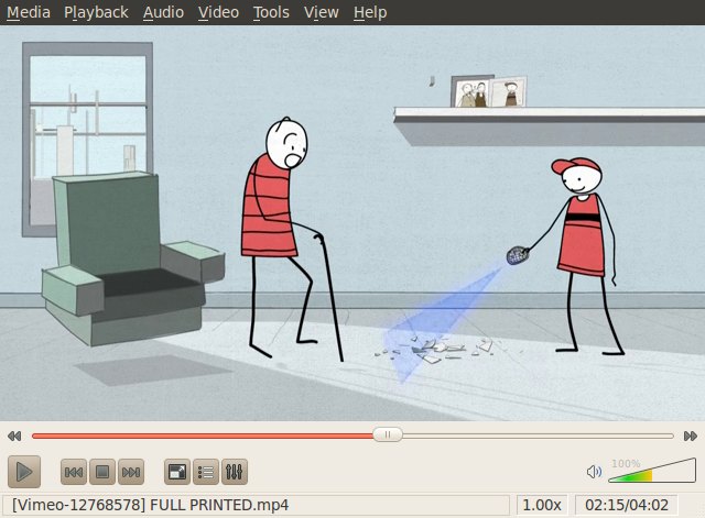
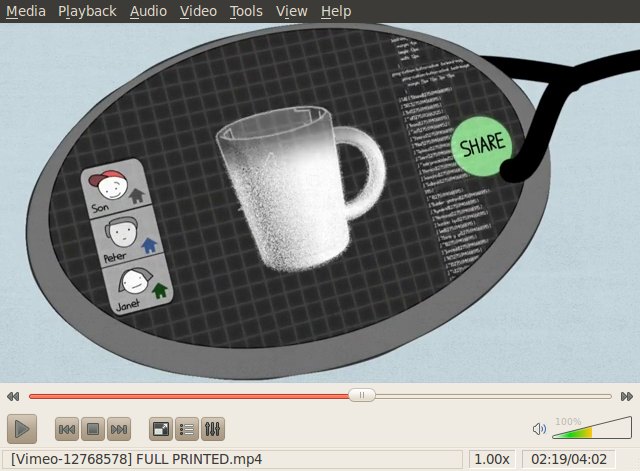
Figures 15, 16: Screenshots of Full Printed, Nueveojos, 2009; https://vimeo.com/12768578
So, these are some pictures of the new 123DCtach scanning process:
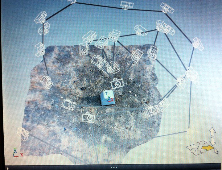
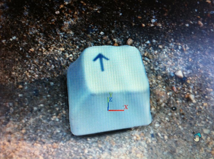
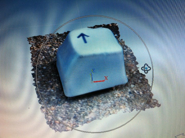
Figures 17-20: One of the original pictures, and 123DCtach screenshots
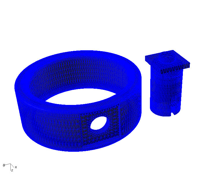
As mentioned, i didn't reprocess the 123DCatch-cloud result, i just cleaned a bit the surroundings and exported it as a .obj file. Next i opened it in Rhinoceros. In Rhino i finished trimming off the lower part [Mesh Edit Tools / Mesh Trim] and then i closed the lower part [Mesh Repair Tools / Fill Hole]. Then i exported it as an .stl file. Rhino told me the .stl was probably not going to be very good for 3D printing. I tried to improve the mesh using several tools, with no apparent success. Eventually i imported the .obj file into the Rhinoceros ring file [one of the baked instances off the Grasshopper file] to check how it would look like. I found out that the scales were different. I had to scale up the 123DCtach generated .obj file with a factor of 2.6, with the result shown in one of the images below.
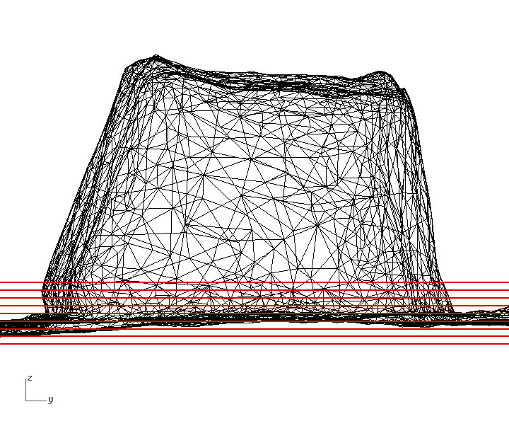
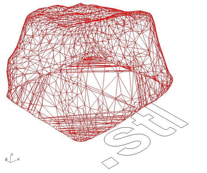
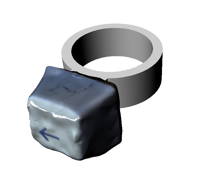
Figures 21-24: Rhinoceros screenshots
[3D printing]
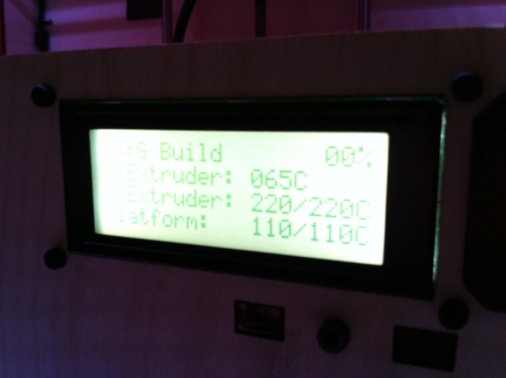
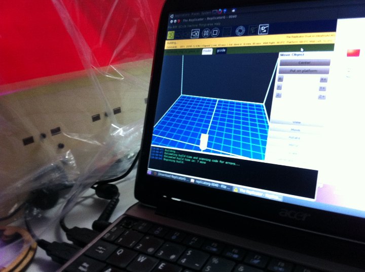
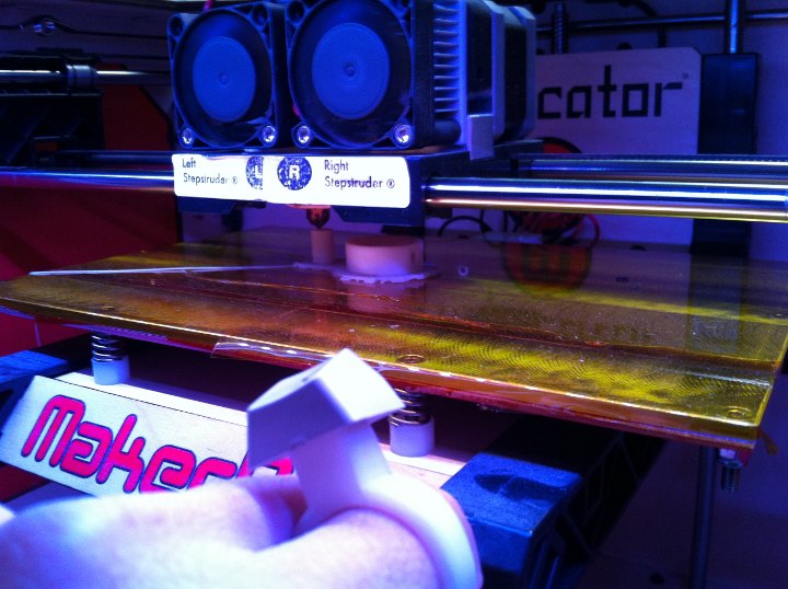
Monday was eventually printing day, and things went quite well. We used a Makerbot Replicator 1, and replicatorg 0040 software. Because the lab these days is rather cold, we implemented an extra heat conservation system, to help the Makerbot keeping the right temperature, that worked quite well. It was an improvised "greenhouse" that we closed and opened depending on temp oscillations in the heated platfrom and extruder. We also watched it carefully while printing. It can be seen in the pictures that the kapton tape over the building platform is not so well placed, and it got worse during the printing day. The resulting prints are not top-top quality but they are quite good. I printed two different variations of the ring design. One of them, as explained before, was made of two pieces that need to adjust quite precisely. It can bee seen in some of the pictures that one of the smaller pieces got a bit flexed in its finer section, probably because of the heat involved in the printing process. Pausing the printing process to let it cool down before finishing the piece could be tried to see if it helps mainating geometric stability. Nevertheless the pieces fitted quite ok. I might give it a little additional sanding to make it fit 100% ok.
After seeing and testing the designs i will incorporate some changes to the next version. I probably will go for the single piece design, changing the "connector-shaft" to make it a bit shorter and slenderer, maybe with a trapezoidal horiozontal section too, but still keeping the flat surface on the z=0 plane to ease the printing process...
Here are some pictures of the printing process and its results:
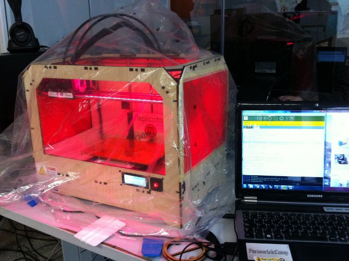
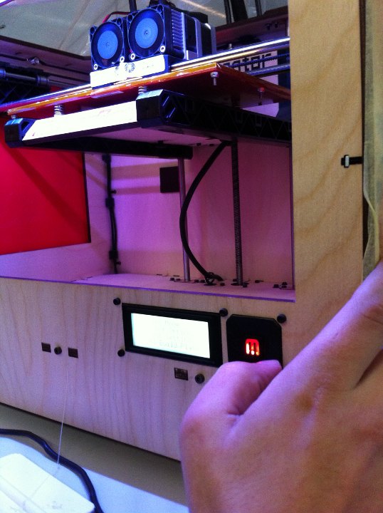
On the left, the improvised greenhouse, to help the Replicator keep the right temperature. On the right, calibrating the heated build platform.
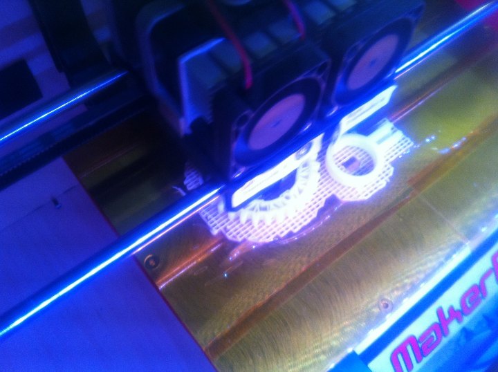
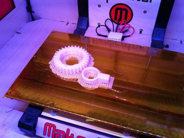
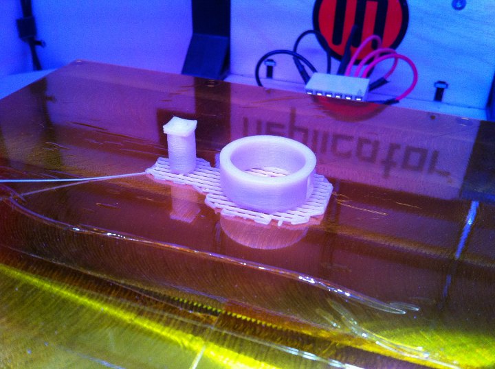
Figures 25-29: Makerbot Replicator 3D printing process of ring 02
Printing two pieces together, one of Jose Buzon's and one of mine. Printing two pieces together takes a little longer considering only printing time, but helps generating a wider raft and also shortens the preliminary heating time.
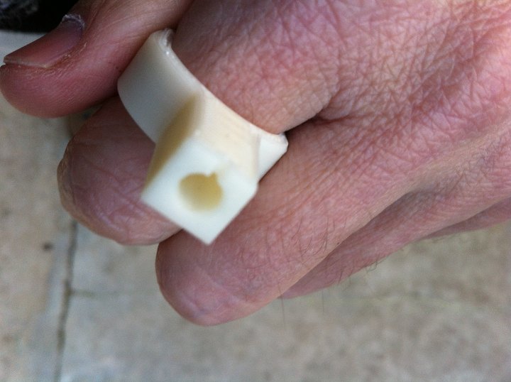
Figures 20-31: 3D printed ring with key fitting in connector
This is the first ring that i printed. It's the one made of a single piece. The connection sistem to the keyboard-key can be apreciated in the left picture.
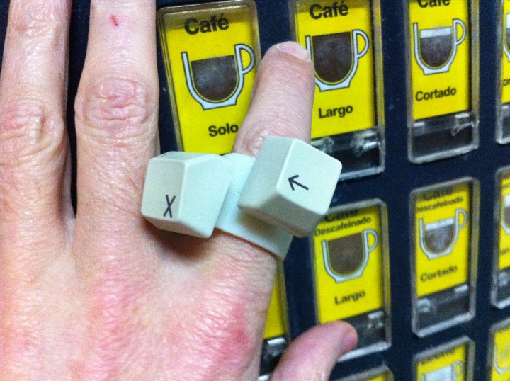
Figures 32-33: Makerbot Replicator 3D printing process of ring 01; and dayly life testing of prototypes
Printing process of the second model, and then buying a cup of coffee!
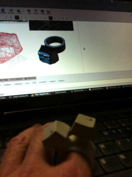
Figure 34: Digital sketch-model and printed rings
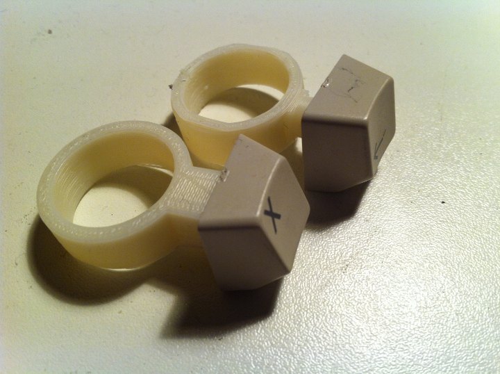
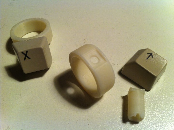
Figures 35-36: Printed rings; assemblages with keys and details
Detail of the printed pieces and keys. The two components of ring 01 can be seen on the right. Notice the curved top of the cylindrical piece which is the small error mentioned before. However, the two pieces do press fit as they came out of the printer.
The parametric design, as explained above, allows to change several parameters, adjusting the design to different finger diameters, as well as to different keys. The length of the connector which came a bit long maybe reduced as well in the parametric model. Grasshopper files are attached to be downloaded in the next section.
[files download]
Information and files are downnloadable under a Creative Commons Attribution-Share A Like license; attribution: Jose Perez de Lama / Fab Lab Sevilla / Fab Academy 2013

# Key_ring version 01; Grasshopper file [.gh_0501]
# Key_ring version 02; Grasshopper file [.gh_0502]
# Key ring versions 01 & 02; Rhinoceros file, ring inner radius = 10mm [.3dm_0502]
# Key ring version 01 .stl file, ring inner radius = 10mm [.stl_0501]
# Key ring version 02 .stl file, ring inner radius = 10mm; beta [.stl_0502]
# Key ring version 01 gcode Makerbot Replicator 1; ring inner radius = 10mm [gcode]
# -> Key 123DCtach .obj file [.obj_05]
Software :: Rhinoceros 4 SR9; Gh 0.9.0014; Replicatorg_0040; profile: Replicator Dual
return home /perezdelama.jose