Fab Lab Barcelona SuperNode /Fab Lab Sevilla /Jose Perez de Lama
Week 04 / 13.02.2013
[assignment]
Fabricate the Fab ISP [In System Programer] PCB: mill the [FR1] board, stuff the components, load the ISP code.
Link to class syllabus & tutorial:
http://academy.cba.mit.edu/classes/electronics_production/index.html
http://fab.cba.mit.edu/content/processes/PCB/modela2.html
[assignment development]
Here starts the part of Fab Academy we were a bit afraid of. At Fab Lab Sevilla we haven't had a lot of experience with electronics. We have organized some workshops with Arduino, but have very little experience with fabricating our own boards, and not at all with fabricating boards with surface-mount components. And they do look extremely tiny! As it is the first time we will be working on this field, the four of us at the lab, Jose Buzon, the two Juan Carlos and myself, decided to team together to get everything in line.
Thursday, the day after the class, we organized a little workshop with Aureliano, the Physics Lab technician at the School of Architecture to learn the theory and practice of soldering. We did practice with some boards that he brought and "through-hole" components. These seemed a delicate task, but somehow easy once you got the right directions and overview. Aureliano is rather skeptical though about our capability of soldering the board with the s-d components... He wants to make them for us, but we insisted that we have to learn to make them by ourselves...
The week before we had tested one of the milling machines in the lab to mill the Fab ISP design on a plastic board. This is a mid size machine, somehow put together by a local workshop. We were not very trustful of its ability to reach the resolution needed by the board, but it did produce a quite promising result. This machine runs with V-Carve Pro software. We checked that it can generate rml files, too; and many others. After the plastic sample we tried to mill an FR4 board, and we broke an old mill right away. We couldn't practice with the right stuff because the FR1 boards ordered from Inventables in the US had been stopped at the customs since last Monday. Too bad! The quality of the milling that was being achieved, however, was quite good.
In the meanwhile we received an iModela that we had ordered from the Arduino store, after doing some research on its capability to mill the boards for this first electronic production assignment and the ones to follow. The main issue seemed to be about finding the right mills, as the shaft diameter of the iModela happens to be an odd one, i.e., 2.35 mm, while the mills in the Fab Inventory have a 1/8" shaft. After quite a while of looking for them, and confirming that are quite a lot of people around milling boards with the iModela [eg Mario Lukas and Massimo Banzi], i found some mills recommended especially for milling PCBs with the iModela at a supplier in the UK, Cool Components. The mills are however, not end mills as recommended, but 45º, engraver, mills. We thought that given the short time, we would have to manage with them. I ordered them and they reached Sevilla in about 4 days. That was pretty good!
Buzon, who is extremely good with all kind of machines put the iModela to work right away, using Windows 7 and Roland's software, I-Creator. We also installed Modela Player 4. The software from Roland is user friendly and simple to understand, especially having some experience with milling machines.
Of course, we connected the iModela to an Ubuntu machine, in order to use Fab Modules to send some files, but were not able to make it work... A message sent to the class list was answered by Guillem from Fab Lab Barcelona, thanks!, and two days later he did send a whole package to make the iModela work with a customized Fab Modules...
In this process we started trying to understand better the workings of Fab Modules png-to-rml program. After reading the various comments in the list and tutorials, we sort of classified the problems to make the Ubuntu+Fab Modules talk to the iModela in three fields: 1, something related to the port in the computer; 2, something related to the format of the files generated by the png-to-rml Fab Module; 3, the problem of moving the mill to the zero point without a physical interface, that the little machine lacks... Indeed, Guillem answered all of this issues. We still have to try the port, but it seems that it was solved by the Barcelona people some time ago.
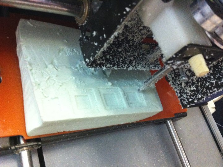
Friday, the four of us spent the whole day in the lab. And with the experience achieved in the class we manage to put to work a Roland Modela MDX-3 that had been in storage for some months, donated by some people that couldn't make it work anymore. We connected the machine and confirmed after some tinkering that the motors responded to the buttons on the top of the machine. As can be seen in the link, it initially worked with Windows 95... We knew that it could work with XP as well. Another little obstacle is that it doesn't have a serial port but a parallel one. We found some drivers for XP, set up an XP machine with a parallel port, downloaded the drivers... Opened a Corel 15 and told it to print... And it worked! It sounds easy, but several people had tried before to no success... Buzon set it up with a mongrel bolt to fix the mill, send a simple design and milled a piece of foam. At some moment, we had the three milling machines working simultaneously. It was fun!
[rml language]
It has been quite fascinating learning about the different files generated by Fab Modules, and particularly deciphering the rml files. I think that now we could generate our own rml files. To achieve this, first we compared the rml files generated by V-Carve Pro and those generated by Fab Modules. Then we generated with Fab Modules a set of files departing from simple geometries that we produced making variations with the cad-to-rml Fab module. In this way we also learned a bit of the .cad code.
Eventually we found a pdf guide to RML language on line, where we could identify all of the commands in the rml files generated by Fab Modules. Here is an explanation of these files for those interested:
| [rml file default
1/64"] First i started with the ISP rml file generated by Fab Modules with the default values for the 1/64" mill. This is a file to cutt the traces of the PCB with a cutting depth of 0.1 mm. The header of this file is as follows: PA;PA;VS4.0;!VZ4.0;!PZ-4,40;!MC1; Where
the meaning of the
different terms is this:
PA;PA;VS4.0;!VZ4.0;!PZ-4,40;!MC1; PA;
PA; absolute coordinates VS4.0; milling
speed = 4 mm/s !VZ4.0; mill
speed in the z axis !PZ-4,40;
movement
range
in
z axis.
Dimensional conversion between mm and the Modela MDX 15-20 for which the Fab Modules files are generated is 40/mm. This is a cue given as well by Guillem. So the range of movement here is from -0.1 mm to 1 mm; -0.1 mm is the cutting depth; 1 mm is when the mill is moving over the board without cutting. !MZ1;
starts the motor. Then come the
orders
or commands to beging the actual milling. The
first line is like this:
PU1568,956;Z1568,956,-4;Z1566,952,-4;Z1569,953,-4;Z1568,956,-4;PU1568,956; PU1568, 956; is Pen Up, to the
coordinate 1568, 956; This
coordinates, where the machine will
start milling, translated into mm [xx/40]
would be: 39.22 mm, 23.90 mm.
I understand these coordinates are
referenced in some way to the 0,0
point that we
are setting at the beginning of the
process, with xmin and ymin. I still have
to confirm this. Then
the next to sections between
"terminators" [;] that separate each
command begin with a Z, followed
by three coordinates, such as: Z1568,956,-4;Z1566,952,-4; !M0;
stops the motor. The
file generated by Fab Modules have
multiple !M0; I am not
sure if all those are needed. H;
finally sends the mill home, to the
original 0,0. [rml
file default 1/32"] This
is a file to cut the perimeter of
the board all the way down, 1.7 mm. The
milling-cutting is performed in
four steps. The
header of this file is as follows: PA;PA;VS4.0;!VZ4.0;!PZ-68,40;!M1; The
difference with the former is only in
the !PZ command. It tells the machine that
the range in the z axis goes
from -68 [-1.7 mm] to 40 [1mm]. Then
if we look at the PUxx,yy;Zxx,yy,zz;
strings we
see that the mill makes four succesive
trajectories one of top of the
other with steps in z as follows: -20
[0.5 mm] Eventually,
the script finishes the same
as the former one: PUxx,yy;!M0;H; So
there are no instrucions in the header
on the z steps, but only the total range
of movement in the z axis.
These have to be looked for then on the
side of Fab Modules and the
parameters incorporated in the default
profile for the 1/32". We
found that the difference that
accounts for this in the default profiles
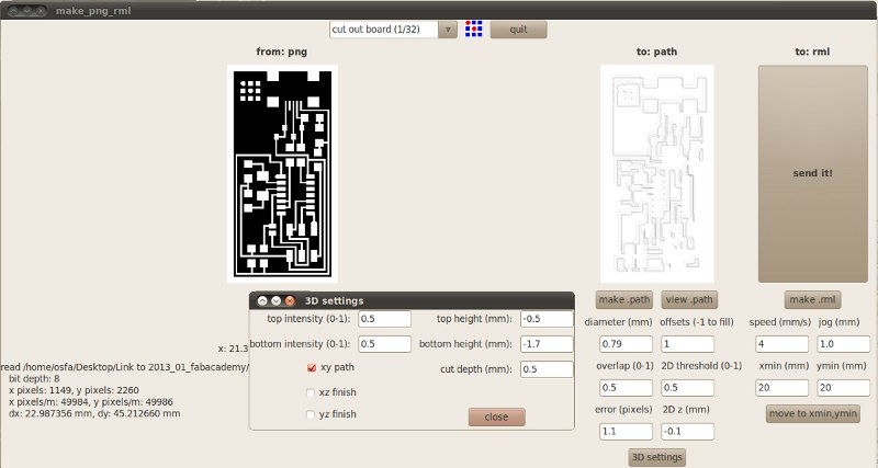
is in the "3D Settings" menu.
Top
height (mm): -0.5 mm [this
corresponds to the first trajectory /
level of cutting Bottom
height (mm): -1.7 mm [corresponds
to the final, lowest level of cutting Cut
depth (mm): 0.5 mm [corresponds to
the dimension of the steps; the final
step, from -1.5 t -1.7 is the
rest after performing two 0.5 steps at
-1.0 and -1.5 mm. Then
the xy path option is selected. The
left parameters top intensity (0-1),
and bottom intensity (0-1) ste both of
them to 0.5 i don't know what
they correspond to. The
2D z (mm) parameter in the main "make
path" menu is set at -0.1, the same as in
the 1/64" deafault profile.
It doesn't seem to play any role in this
case. A
comparison between the parameters in
the two default profiles can be seen in
the two following tables: 3D
settings menu
|
[ISP board design]
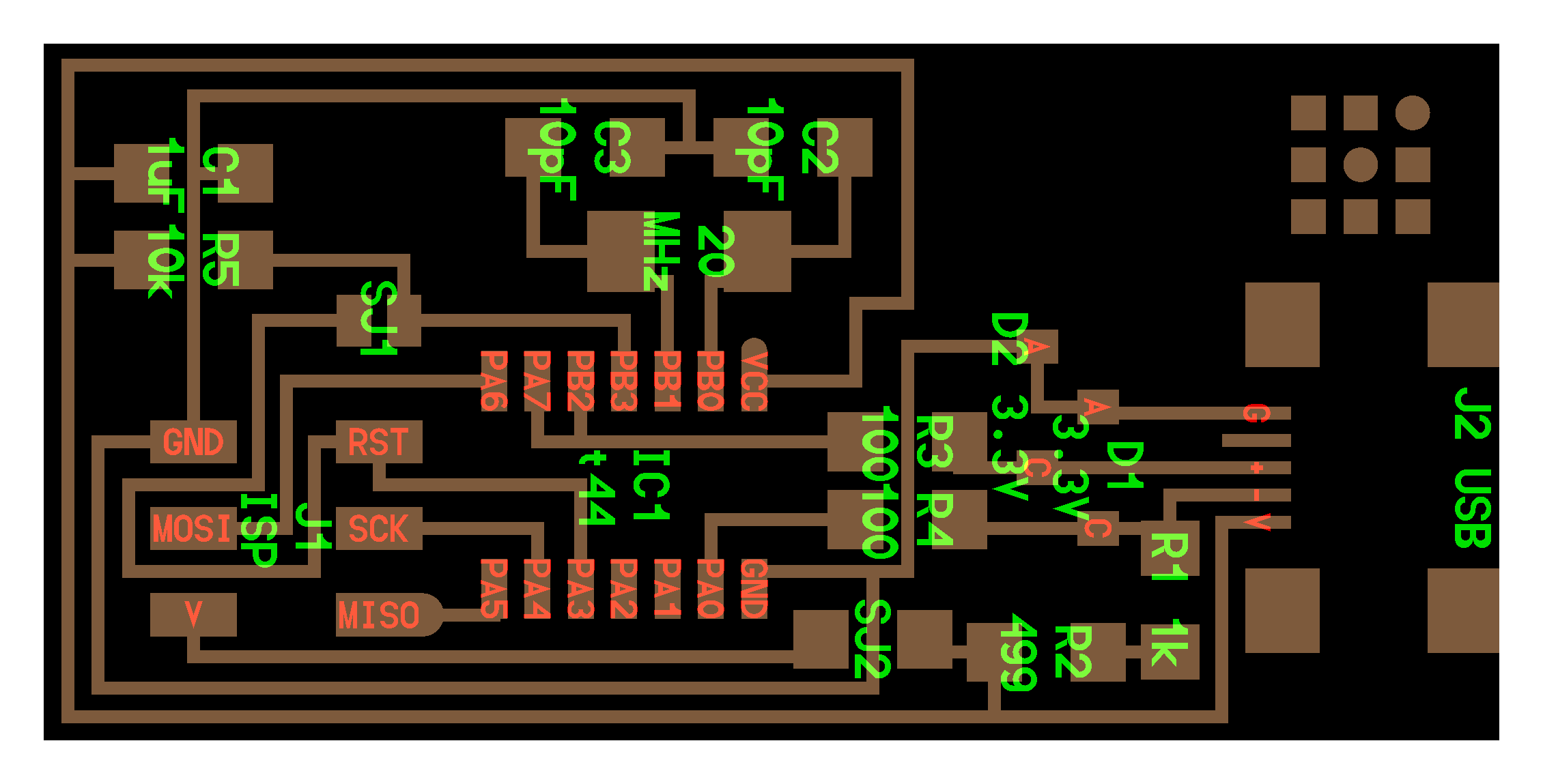
This is the PCB we are supposed to fabricate and program. It is an In-System-Programer, which means, that it is a board that is used to program other boards/microcontrollers. More precisely this means that one uses the ISP to load a program into the microcontroller of another board. Some people tell me that this was a difficult and expensive task some years ago. Now you can do it as well with an Arduino board. At least in some cases.
There are several variations on the Fab ISP in the class file. We chose the main one recommended by NG, which incorporates a "crystal". Another one has a resonator instead. There are at least three other models designed by MIT folks with interesting variations / improvements [link to the class at the beginning of the page].
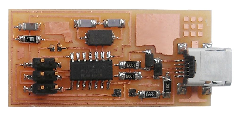
This is the board then; [1] visual description with components; [2] image of an actual PCB; [3] and [4] pngs with traces, and perimeter to mill with the Modelas.
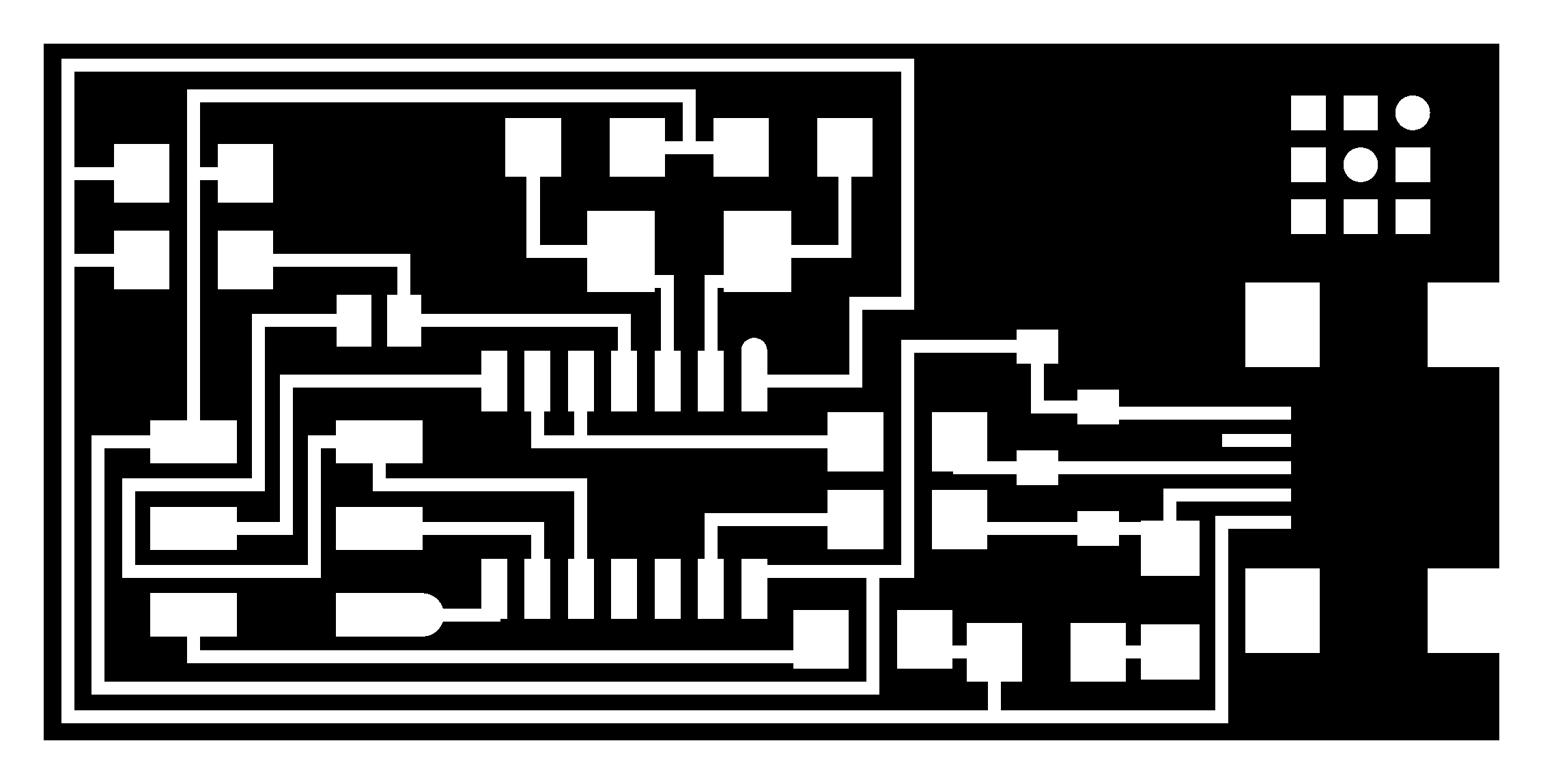

Figures 02, 03, 04, 05: Fab ISP board 44
The components to "stuff" the ISP board with are as follow. The list has been determined, together with Heloisa Neves, contrasting the class information, the specs in the first png and the fab inventory. Here again is a table with the components and other necessary materials:
| Microcontroller |
||
| Num.
units |
Element |
Digikey
ref. |
| 1 |
IC1 tt4 / ATTINY44A; IC MCU AVR 4K FLASH 20MHZ 14SOIC | ATTINY44A-SSU-ND |
| Resistors | ||
| Num.
units |
Element |
Digikey
ref. |
| 1 |
R1 1K / RES 1.00K OHM 14W 1% 1206 SMD | 311-1.00KFRCT-ND |
| 1 |
R2
499 / RES 499 OHM 14W 1% 1206 SMD |
311-499FRCT-ND |
| 2 |
R3,
R4 100 / RES 100 OHM 14W 1% 1206 SMD |
311-100FRCT-ND |
| 1 |
R5
10K / RES 10.0K OHM 14W 1% 1206 SMD |
311-10.0KFRCT-ND |
| Jumpers |
||
| Num.
units. |
Element |
Digikey
ref. |
| 2 |
SJ1,
SJ2
/ RES 0.0 OHM 14W 5% 1206 SMD |
311-0.0ERCT-ND |
| Diodes |
||
| Num.
units. |
Element | Digikey
ref. |
| 2 |
D1,
D2 3.3V / DIODE ZENER 500MW 3.3V SOD123 |
BZT52C3V3-FDICT-ND |
| Capacitors |
||
| Num. units. | Element | Digikey ref. |
| 1 |
C1
1uF / CAP CER 1UF 50V X7R 10% 1206- |
445-1423-1-ND |
| 2 |
C2,
C3 10pF / CAP CERAMIC 10PF 50V NP0 1206-$0.03612-
|
311-1150-1-ND |
| Crystal |
||
| Num. units. | Element | Digikey ref. |
| 1 |
Crystal
20
MHz / CRYSTAL 20.000000 MHZ 8PF SMD |
644-1039-1-ND |
| Connectors |
||
| Num. units. | Element | Digikey ref. |
| 1 |
J2
USB / Mini USB connector / |
H2961CT-ND |
| 1 |
J1
ISP header / 2x3 connectors / BERGSTIK HDR 10POS
.100" DR SMT or CONN
HEADER 4POS .100" DL SMD |
609-3483-6-ND
or
609-4463-6-ND |
| 1 |
Ribbon
connector
/ CONN SOCKET IDC 6POS DL SR 30AU |
609-2841-ND |
| Other |
||
| Num. units. | Element | Digikey ref. |
| 1 |
USB
mini cable connector / CBL USB A-MNI B CON 3'
28/28 AWG |
Q362-ND |
| 1 |
Ribbon
cable
6 connectors |
xx |
| PCB |
||
| FR1
blank PCB board, 22.9*45.21 mm |
Inventables,
Fab Lab Network |
[tests images]
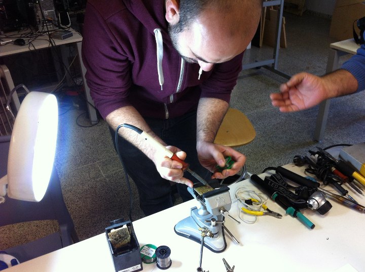
Figures 06, 07: Jose Buzon in the soldering class, working with "through hole" components. 07, right, our first soldered PCB, a team work of Jose Buzon and myself, with directions of Aureliano.
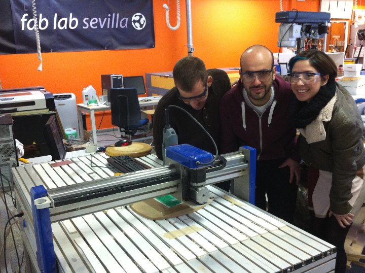
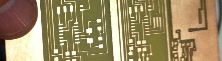
Figures 08, 09: Jose Buzon, Juan Carlos Venegas and Yolanda R testing the Alaris milling machine on a painted polypropilene sheet. We used an old mill. The resolution, surprisingly was quite satisfactory. Software used was V-Carve Pro together with the prorietary machine driver.
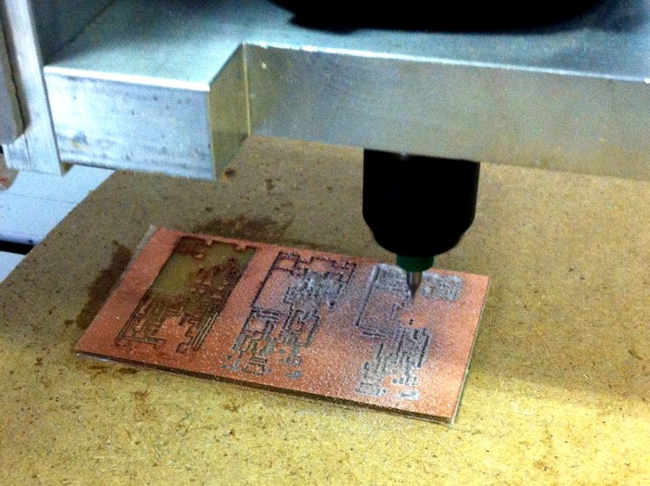
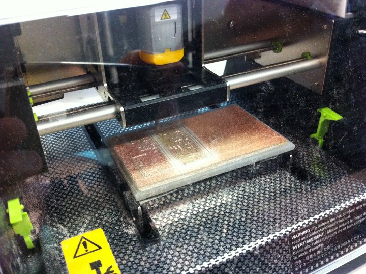
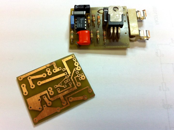
Figure 10, 11: Left, a further test with the Alaris on an FR4 board, after having broken one of the old mills; and, right, a first test with the iModela with an FR4 board and a 0.2mm 45º mill. Here we were using the iModela driver and software, iCreator [image below]. The file we processed through Rhinoceros to generate an .ai file to send to the iModela. We did try to communicate the iModela with Fab Modules but weren't able to achieve it yet. We will go back to it on Monday with the code and directions sent by Guillem from Fab Lab Barcelona.
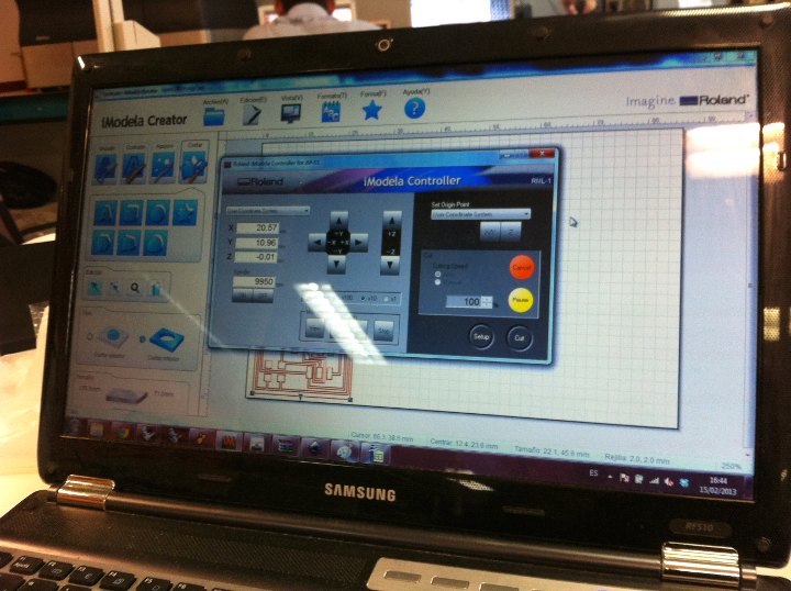
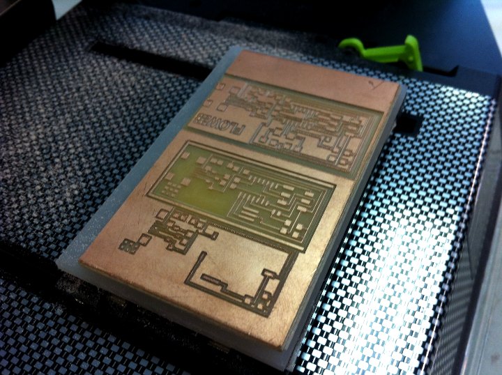
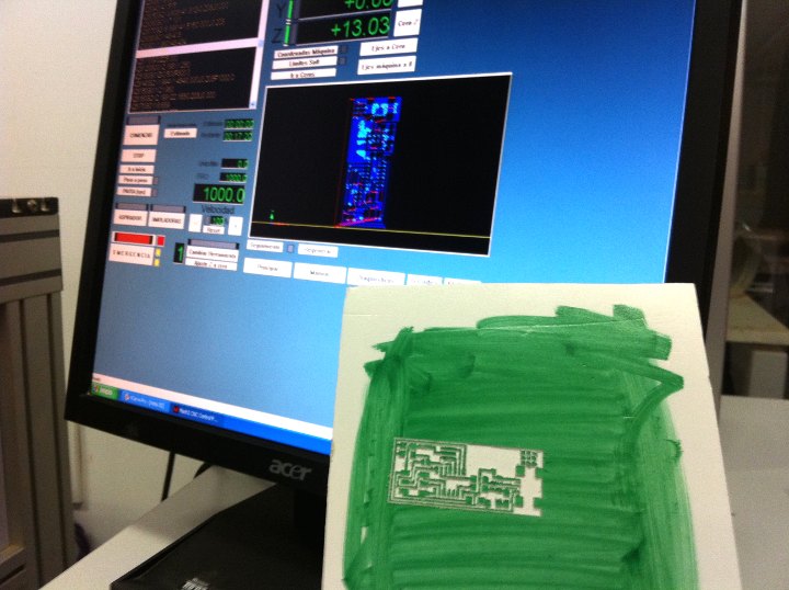
Figure 11, 12: ICreator screenshot, and various tests with the iModela. The third board is a larger version of the board that we drew with Inkscape + Rhinoceros, thinking that it would be easier to solder; but of course it took much longer. It can be seen in the second board that the tracks and components have become too small, probably because of having chosen a wrong milling configuaration and/or the 45º profile of the mill we were using.
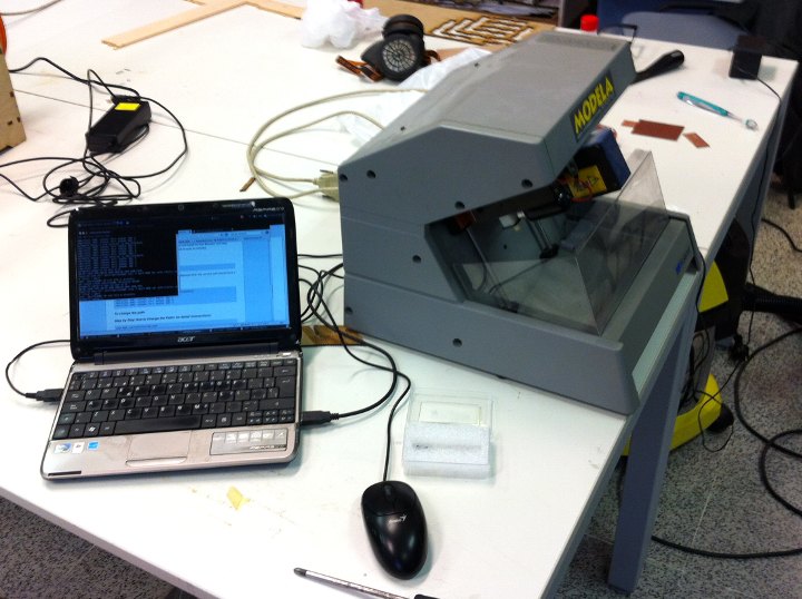
Figures 13, 14: Trying to communicate Fab Modules on an Ubuntu machine with the old Modela MDX-3. 14, right: The MDX-3 working, on Windows XP, proprietary drivers and Corel 15, and a parallel port, after many years of being idle. This was a happy moment late Friday night... Next, we will try to make it work with Fab Modules...
[generating the CAM files; studying the paths...]
After the not completely succesful tests made Thursday and Friday i decided to learn better how paths should be designed and generated. This is of course connected to the part above on rml. I was playing around with Fab Modules, testing various parameters, and comparing the png files generated, the path text files where the paths are numerically described and the rml files where they are translated into Modela code. I also was checking the fab_send file, and trying to understandd issues concerning the ports to be used in the different machines: usb, serial, and parallel for the iModela, and how to select/configure them using the terminal.
What i was rtrying to find out is what kind of changes to the defualt configuration should we make in order to mill and get the right results with the 0.2mm 45º mill, insteaed of the recommended, but not available to us now, 1/64" end mill.
On one hand i was studying the paths generated by the default configurations and the ISP file, and the other i think i figured out the changes i had to introduce to mill with the alternative bit. Here are some images on this.
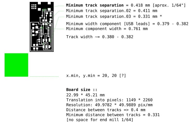
Figure 15: General dimensional parameters of the board. The green square represents the 0,0 point as given in the default configuration of Fab Modules.
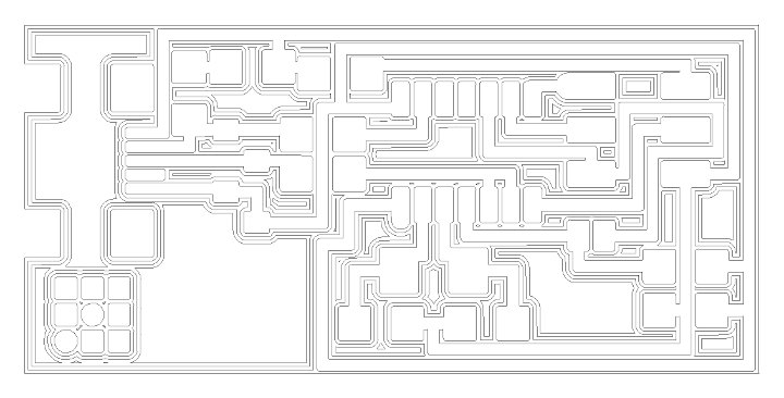
Figure 16: Milling paths for the default configuration as generated by Fab Modules. Default configuration correspond to Diameter = 0.4mm [1/64"], Offsets = 4, Overlap = 0.5. The pixel error parameter i don't understand yet.
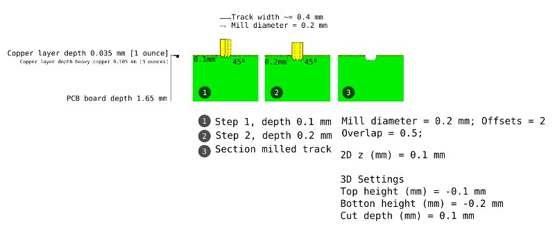
Figure 17: Diagram; 0.2 mm diameter mill and 0.4 mm width track geometry
This is a diagram, a bit too small here, of the geometry of the 0.2mm 45º mill cutting a trach, that has an average width of 0.4mm. The depth of the copper layer is also represented. The image represents an overlap of 0.5. Three paths would make a sufficient milling. A cutting depth of -0.1mm should be enough even with the angle, given that the geometry of the mill were exactly 45º after some wearing. A cutting depth of 0.2mm should be enough in any circunstance.
The following path maps correspond to files generated with Fab Modules. The first one with a 0.2 mm diameter mill and Offset value of 2, that i think would determine what is drawn above. The second one corresponds to the same mill and and Offset value of -1, that fills, or rather empties, all the free spaces in the board. We will try this parameter configurations tomorrow, Monday.
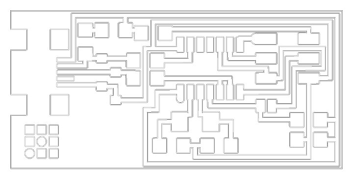
Figure 18: Fab Modules generated milling paths for parameter values Diameter = 0.2, Overlap = 0.5; Offsets = 2
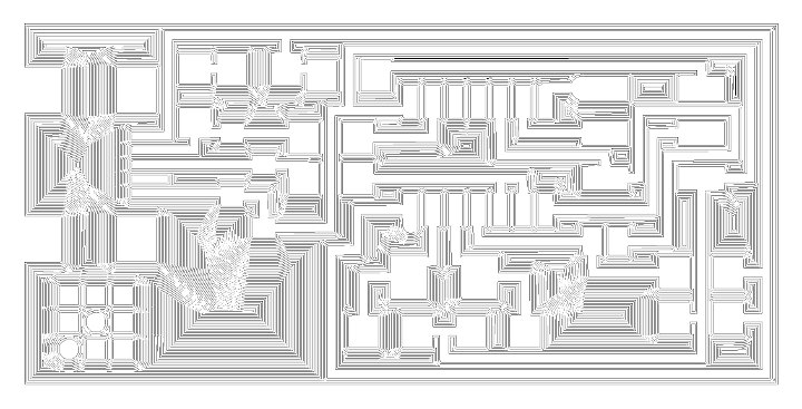
Figure 19: Fab Modules generated milling paths for parameter values Diameter = 0.2, Overlap = 0.5; Offsets = -1 [fill]
[additional work]
I didn't get the hello fabISP board to work, but i tried hard and several times. In later weeks i did manage to master the process of PCB milling as well as the bootloading tool chain using the AVRisp mkII. Towards the end of the Academy [final project] we also got a special adapter for the iModela that allowed us to use the 1/64" end mills, which made a big difference; even if the mills last for very short time [three to five boards per end mill].
///
Information and files are downloadable under a Creative Commons Attribution-Share A Like license

#
#
return home /perezdelama.jose