Final Project : Interactive “Bris Soleil” for Solar Shading

Interactive “Bris Soleil”

Work In Progress:

13-Fa-PF-V06

13-Fa-PF-V04

http://en.wikipedia.org/wiki/Brise_soleil

Reference:

Evolución del Brise Soleil en la obra de Le Corbusier

http://www.sostenibilidadyarquitectura.com/index.php/proyectos/26-referencias-significativas/34-evolucion-del-brise-soleil-en-la-obra-de-le-corbusier

Inspirations:

http://www.hoberman.com/news.html

HelioTrace receives 2010 R+D Awards citation

http://www.architectmagazine.com/building-envelope/2010-rd-awards-heliotrace-facade-system.aspx

http://www.hoberman.com/portfolio/heliotrace.php?projectname=HelioTrace

http://www.hoberman.com/abi.html

http://www.adaptivebuildings.com/

Focus:

Designing a new generation of buildings that optimize their configuration in real time by responding to environmental changes.
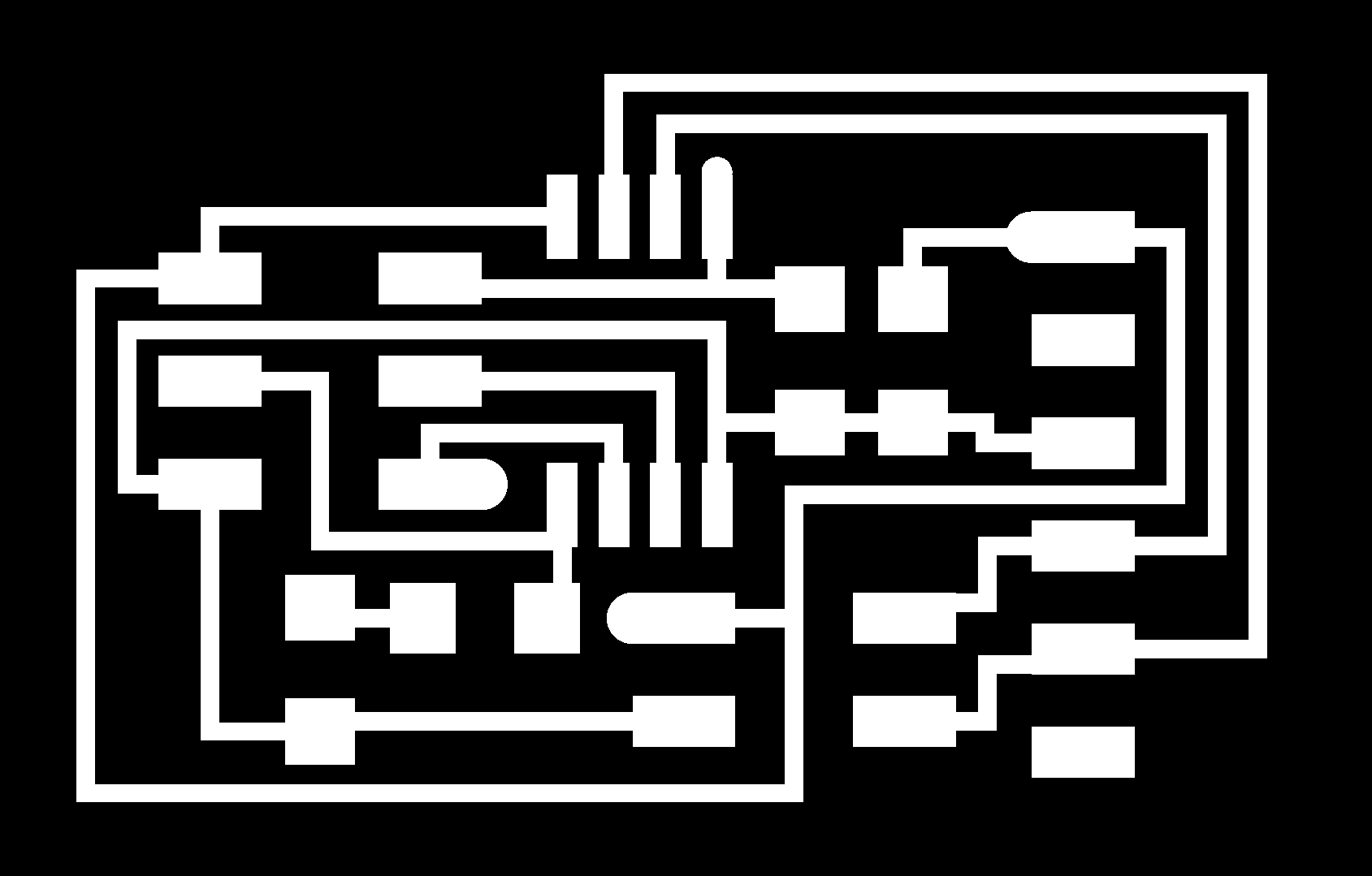
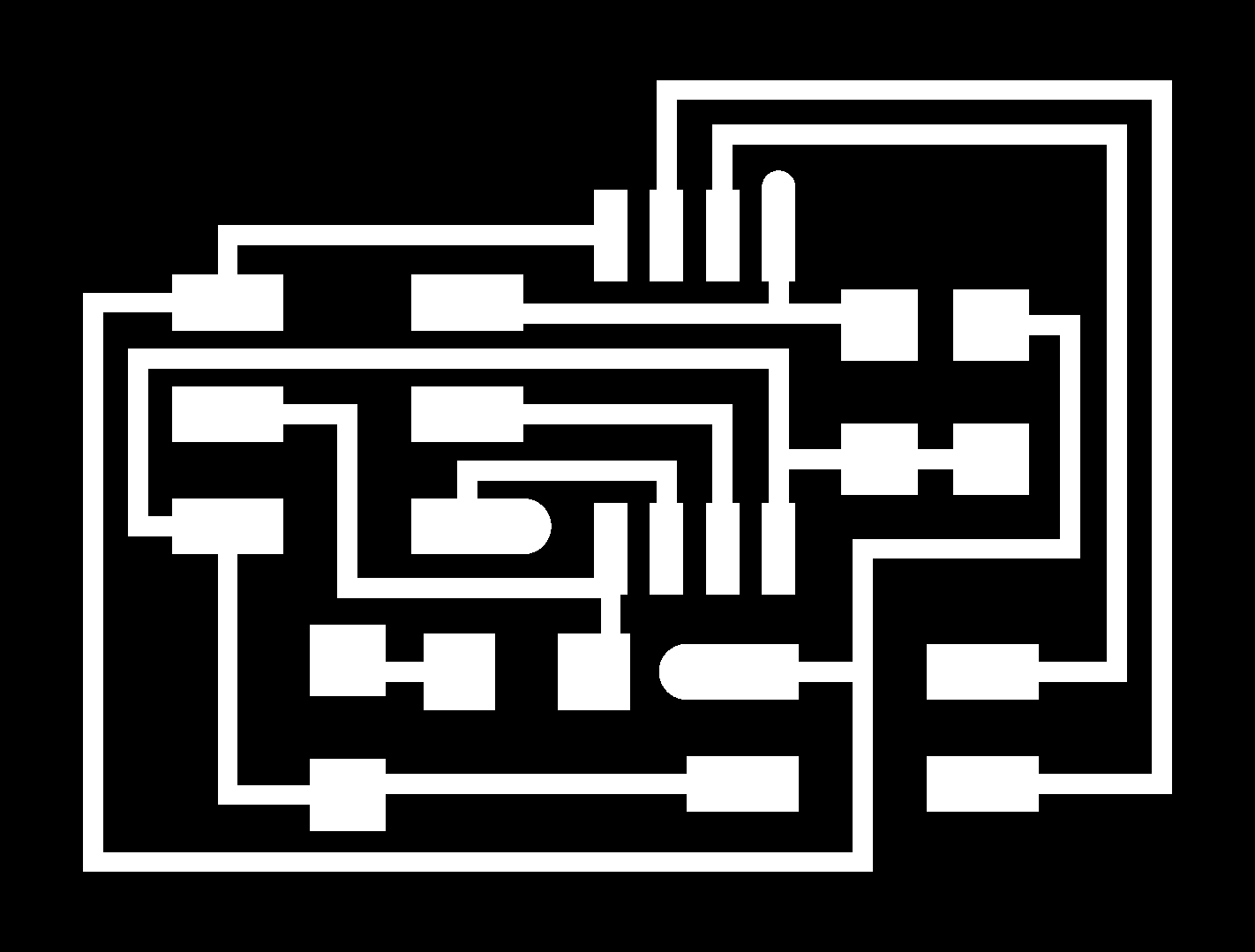
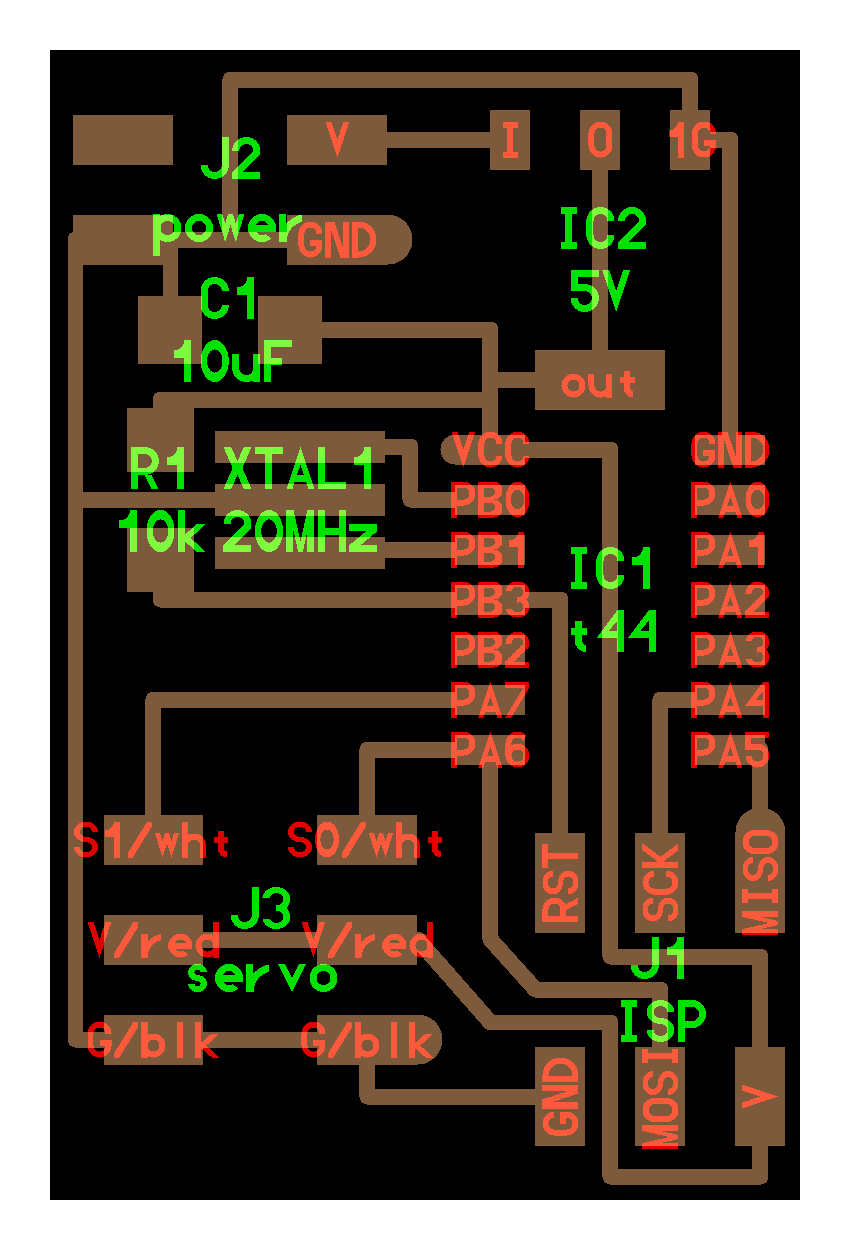
Sketch 01

Diagram: by Juan Ranera

image

13-Fa-PF-V10

Images of the Model in Grasshopper

13-Fa-PF-V25 13-Fa-PF-V26 13-Fa-PF-V24 13-Fa-PF-V13 13-Fa-PF-V16


Components:

1-poleas http://www.mcmaster.com/#pulleys/=mlkib1

http://www.mcmaster.com/#pulleys/=mmupwa

2-mediante correas de plástico http://www.mcmaster.com/#timing-belts/=mlkjhr

3-motor unipolar. paso a paso o stepper http://www.cursomicros.com/avr/puertos/motores-paso-a-paso.html.

“output_devices” (stepper_motor ->unipolar)

4-Sensores de luz

5-Sensores de temperatura

6-codigo con factor de histéresis para evitar movimientos bruscos al llegar al umbral de temperatura o de luz definido.


assignment on progress:
plan and document a final project that integrates the range of units covered:
what will it do?
who’s done what beforehand?
what materials and components will be required?
where will they come from?
how much will it cost?
what parts and systems will be made?
what processes will be used?
what tasks need to be completed?
what questions need to be answered?
what is the schedule?
how will it be evaluated?

What will it do?
Materials, From where?, Cost?
Parts and Systems:
Motor paso a paso

http://es.wikipedia.org/wiki/Motor_paso_a_paso

http://academy.cba.mit.edu/classes/output_devices/index.html

http://en.wikipedia.org/wiki/Stepper_motor

Processes:
Tasks:
Questions?
Schedule:
Evaluate?

Networking and Communications

http://academy.cba.mit.edu/classes/networking_communications/index.html

assignment
   build a wired &/or wireless network with at least two nodes

Tutorial:

http://fabacademy.org/content/tutorials/15_Networking_and_Communications/Hello_Serial_Bus_C.html


http://www.as220.org/fabacademy/tutorials/networking_serial_bus.php

Network several boards together in the form of a serial bus.
Components:
1-FTDI cable
2-the FabISP in-circuit programmer ( I used the ATAVRISP2 ) (whit my FabISP it did not work)

http://www.atmel.com/tools/AVRISPMKII.aspx

3-Bridge 0 
4-Node 1 ( I did two Nodes)
Download the PNG files (bridge and node) board (traces and Interior) to mill the boards on the Modela 
and then soldering all the components.

http://academy.cba.mit.edu/classes/networking_communications/index.html

bus
   asynchronous
      RS-232, RS-422, RS-485
      components video
      hello.bus.45.bridge.cad board traces interior
      hello.bus.45.node.cad board traces interior
      hello.bus.45.c makefile
 
IMG_2821 IMG_2823

IMG_2826 IMG_2830

Get the Board Files and Code

NOTE: There is an issue with Neil’s C code compiling / use this code instead

Download the CCode from here

http://www.as220.org/fabacademy/tutorials/networking_serial_bus.php

connect the programer to the computer 
(the FabISP in-circuit programmer I used the ATAVRISP2 )
and connect the bridge. 
(note: control the directions of the ground and the black line of the FTDI cable)  
open the file hello.bus.45.c 
whit the Xcode and change the code : to ´0´ and save the file

#define node_id '0'
Then on the Terminal go to the folder and run 
sudo make -f hello.bus.45.make program-usbtiny
Connect the Node Board (whit the 6-pin Socket/Socket IDC cable - 6") 
(note: connect the red line to the voltage)
Whit the Bridge Board and with the programer. 
Open again the file hello.bus.45.c and change the number for 1 for the first node
and do it again for each node

Open Arduino , Check the port and Open the Serial Monitor in the Tools menu.
then write the number of the node 0,1,2..
and the led has to blink.
 Terminal-done NetWorking-Arduino-test-ok
NetWorking-done
 

Output Devices

http://academy.cba.mit.edu/classes/output_devices/index.html

assignment
   add an output device to a microcontroller board and program it to do something


I did the Barduino Board

http://fabacademy.org/content/projects/barduino/index.html

and the Servo  Motor board.

http://academy.cba.mit.edu/classes/output_devices/index.html


servo
   hello.servo.44.cad board components traces interior
   C (hardware PWM) makefile C (two-channel, software PWM) makefile video

But First I test how to interact between a Photoresistor LDR and the  movement of the Steper Motor 
with an Arduino UNO.
In the Code setting the average of measures of the LDR 
to a range of degrees for the movements of the Servo motor from 0 to 180 degrees

http://en.wikipedia.org/wiki/Photoresistor

The motor a use was an Analog Servo ref SO150
TORQUE ( kg-cm): 14 @4.8v, 15.5 @ 6v 
Metal gears 
Function speed (sec/60º): 0.14 @ 4.8v, 0.13 @ 6v 
Dimensions: 40.8x20.1x38 mm 
Weight: 54 grams
http://www.hobbyking.com/hobbyking/store/__84__189__Servos_and_parts-All_Servos.html

http://www.rctecnic.com/


http://www.rctecnic.com/en/online-shop/details/831/174/servos/servos-estandar-30-55gr/servo-digital-rctecnic-s0150f--15kg-estandar-metalico
I Use fritzing to do the schematic

http://fritzing.org/

FA-Arduino-LCD-Sensor-ServoMotor
IMG_3567 IMG_3579 

IMG_3581

A first video of this step:


I copy the Code as I have it until now:

// Sweep
// by BARRAGAN <http://barraganstudio.com> 
// This example code is in the public domain.

#include <Servo.h> 

Servo myservo;  // create servo object to control a servo 
                // a maximum of eight servo objects can be created 

int pos = 0;    // variable to store the servo position 
int var = 0; 
void setup() 
{ 
    Serial.begin(9600);
  myservo.attach(9);  // attaches the servo on pin 9 to the servo object 
} 

void loop() 
{ 

    // read the input on analog pin 0:
  int sensorValue = analogRead(A0);
  // Convert the analog reading (which goes from 0 - 1023) to a voltage (0 - 5V):
  float voltage = sensorValue; //* (3.3 / 100.0);
  // print out the value you read:
  //Serial.println(voltage);
   //     delay(15);
 /*       
  if(voltage <= 40) myservo.write(0); 
  if(voltage >40) myservo.write(180); 
*/
  if(voltage <= 20) var=1;
  if((voltage > 20) && (voltage<=60))  var=2;
  if(voltage > 60)  var=3;

 switch (var) {
    case 1:
          myservo.write(0); //0 grados
      break;
    case 2:
          myservo.write(90); //180 grados
      break;
    case 3:
          myservo.write(180); //90 grados
      break;
    case 4:
          myservo.write(220);
      break;
    case 5:
          myservo.write(280);
      break;
  }

      //  myservo.write(voltage); 
        //delay(15);
 /* 
  for(pos = 0; pos < 180; pos += 1)  // goes from 0 degrees to 180 degrees 
  {                                  // in steps of 1 degree 
    myservo.write(pos);              // tell servo to go to position in variable 'pos' 
    delay(15);                       // waits 15ms for the servo to reach the position 
  } 
  for(pos = 180; pos>=1; pos-=1)     // goes from 180 degrees to 0 degrees 
  {                                
    myservo.write(pos);              // tell servo to go to position in variable 'pos' 
    delay(15);                       // waits 15ms for the servo to reach the position 
  }
 */ 
} 

References:

http://arduino.cc/es/Reference/SwitchCase


http://www.arduteka.com/2011/11/tutorial-arduino-0004-sensor-ldr/

Interface and Application Programming

http://academy.cba.mit.edu/classes/interface_application_programming/index.html


assignment
   write an application that interfaces with an input &/or output device

This week I began installing processing and doing some tutorials:

http://lab.modecollective.nu/lab/introduction-to-processing/

and I start to study some books about processing: Getting Started with Processing by Casey Reas & Ben Fry and Programming Interactivity Joshua Noble.

Getting Started with ProcessingProgramming Interactivity Joshua Noble

Then I started to study the FireFly plugin for grasshopper

http://fireflyexperiments.com/resources/

Firefly for Grasshopper / Arduino

case of studies and some places I found:
First Firefly Test_Photocell Sensing and Basic Grasshopper Louvre System

Behavior Study 3: Sensor Override

http://www.alivingarchitecture.com/category/experiments/

then I did the Barduino Board:

http://www.fabacademy.org/content/projects/barduino/index.html

http://www.fabacademy.org/content/projects/barduino/images/pinout.jpg

Steps.

1.Connect the Barduino board with an FDI Cable and  program your board, simply connect it to your fabISP (beware of orientation) and to a power supply (your laptop)

IMG_3115

IMG_3116


2-in Arduinio run the Burn Bootloader from Tools

3-Tools / Select your serial port

4-Tools / Board and select the Arduino Pro or Pro Mini (5V, 16MHz) w/ ATMega 328


IMG_3044


IMG_3045

5- test the Barduino Board with the Blink File, open it from File / Examples/ Basics an run it with the Pin 13.

Blink


IMG_3043

6-Conect a Bread Board and connect the ground  to the – line in the Bread Board and the 5v to the red lines as show in the photo.

see the jpg  http://www.fabacademy.org/content/projects/barduino/images/pinout.jpg

Download fritzing from http://fritzing.org/ to do the schematic if you want.

7-Connect a sensor of light and a resistance

screen-capture-245

IMG_3060 IMG_3061

8-In Arduino Open the AnalogReadSerial File and load it and run it:

/*
AnalogReadSerial
Reads an analog input on pin 0, prints the result to the serial monitor.
Attach the center pin of a potentiometer to pin A0, and the outside pins to +5V and ground.

This example code is in the public domain.
*/

// the setup routine runs once when you press reset:
void setup() {
// initialize serial communication at 9600 bits per second:
Serial.begin(9600);
}

// the loop routine runs over and over again forever:
void loop() {
// read the input on analog pin 0:
int sensorValue = analogRead(A0);
// print out the value you read:

int sensorClean=map(sensorValue, 190, 640, 0, 100);
sensorClean = constrain(sensorValue, 0, 255);

Serial.print(“RAW: “);
Serial.print(sensorValue);
Serial.print(“CLEAN: “);
Serial.println(sensorClean);
delay(1000);        // delay in between reads for stability
}

9-Open Processing and Open the Input and Graph file,a copy the code here:

import processing.serial.*;

Serial myPort;        // The serial port
int xPos = 1;         // horizontal position of the graph

void setup () {
size(800, 300);
println(Serial.list());
myPort = new Serial(this, Serial.list()[0], 9600);
myPort.bufferUntil(‘\n’);
background(0);
}

void draw () {
}

void serialEvent (Serial myPort) {
String inString = myPort.readStringUntil(‘\n’);

if (inString != null) {
inString = trim(inString);
float inByte = float(inString);
println(inByte);
inByte = map(inByte, 0, 300, 5, height);
stroke(0,255,0);
line(xPos, height, xPos, height – inByte);
if (xPos >= width) {
xPos = 0;
background(0);
}
else {
xPos++;
}
}
}


IMG_3067screen-capture-234


10. touch the sensor and you could see the graph moving. changing the size of the Lines.

you could map the range of number received from the sensor.

screen-capture-237


Composites

http://academy.cba.mit.edu/classes/composites/index.html
assignment
   design and make a 3D mold, and produce a fiber composite part in it

http://www.westsystem.com/ss/assets/HowTo-Publications/Vacuum-Bagging-Techniques.pdf

V-03

13-FA-Proyecto-01-001.011

13-FA-Proyecto-01-001.013

13-FA-Proyecto-01-001.012

13-FA-Proyecto-01-001-f..014

Vacuum Bag Technique


Process and References

As I am doing the FabAcademy in Barcelona, I have been visiting and studying the works by Gaudi, When you see his works behind his textures and colors you find geometries in relation with structure and I admire him because he did what he did without computers and without digital fabrication.

I have been very interested in the way he develops ruled surfaces, and senoidal surfaces and I found a deep interest subject  in his work with the finding form process, using loads in catenaries and then inverting the arcs. and finding optimal structural forms.

so In this assignment, I would like to do a modest tribute to Gaudi and his finding form process.  with catenaries so I start to work with grasshopper to do a series of tree catenaries, one of them in the middle with the weight up inverting the direction of the vector  z and I loft them generating a simple double curve surface. this is a subject that I will like to work on later in real scales. I did  a  simple double surface  in order to mold it in wood.

Process

1- Grasshopper Definition + Rhino Model

2-Export a .STL and open the File in PartWorks to setup the ShopBot PRSalpha CNC an mill the mold in a Foam.

http://www.shopbottools.com/mProducts/prSalpha.htm

http://www.shopbottools.com/msupport/tutorials.htm

3- I unrolled the surface of the model in order to cut It , I use in Rhino the

the layer of Wood with the CNC Multicam 2000 ,

4-The Rhino FIle I Exported to DXF and open it in the software enroute http://www.enroutesoftware.com/default.aspx

see a tutorial here : http://www.youtube.com/watch?v=xqRU35lCBsU

I set up the speed 45 and power 180 to cut wood of 1mm

we test first fibre and cotton

for the fibre I setup the speed in 55 and the power in 80

for the cotton I setup the speed in 60 and the power in 40

5. I mill the mold in foam in a Shopbot using PartWorks

http://www.shopbottools.com/msupport/tutorials.htm

6-and then I put the resin in the wood and then on the mold using plastic between the mold and the wood

Super Sap CLR Epoxy (2) + Super Sap  CLF hardener (1)

http://entropyresins.com/landing-page

http://www.entropyresins.eu/product/super-sap-clr-clf-cls

7. I put all together inside the Vacumm Bag, turn on the air compressor and wait for 6 hours.


Input Devices

http://academy.cba.mit.edu/classes/input_devices/index.html


assignment
   measure something: add a sensor to a microcontroller board and read it

http://academy.cba.mit.edu/content/tutorials/

http://academy.cba.mit.edu/content/tutorials/11_Input_Devices/Input_Device_Examples_C.html

http://academy.cba.mit.edu/classes/input_devices/index.html

sound IMG_2277 IMG_2278 IMG_2280 IMG_2282IMG_2281


In the first part of the week, I wanted to measure distances with a ultrasonic sensor :

sonar
   ultrasonic transmitter, receiver

http://www.jameco.com/webapp/wcs/stores/servlet/ProductDisplay?langId=-1&storeId=10001&catalogId=10001&productId=139492

I found this tutorial

http://www.micro-examples.com/public/microex-navig/doc/090-ultrasonic-ranger.html

http://www.micro-examples.com/pics/090-ULTRASONIC-RANGER-schematic.png

I did in Eagle the Schematic but some of the components were not in the FabLab and I did not how to changed for others, Honestly I have to tell that my knowledge of electronics are null.

So today I did the sound board, following the steps with the machine and so on, but when I program the board it give me an error= Error 1 and I have not yet found what happen It seems that I have something wrong in the board.

hellomic45-Error1

How to Program the Sound Board:

Tutorials:

http://academy.kaziunas.com/tutorials/Datasheets/11.html

http://academy.cba.mit.edu/2012/labs/providence/tutorials/11.html


Process:

if using a Mac you need PySerial 
Install PySerial on Mac OS X: http://pyserial.sourceforge.net/pyserial.html
PySerial
To get avrdude and GCC on Mac OS:

http://academy.cba.mit.edu/2012/labs/providence/tutorials/05.html


http://www.obdev.at/products/crosspack/index.html


http://www.obdev.at/products/crosspack/download.html

install
CrossPack-AVR-20130212.dmg 

I did the 

Computer-Controlled Machining

http://academy.cba.mit.edu/classes/computer_machining/index.html

assignment
   make something big

Constraint: The Material could not be buy it has to be find on the street.

This is a Big Idea, that FabLabs help in the process of recycling materials in the City.

recycle:
convert (waste) into reusable material : car hulks were recycled into new steel | [as adj. ] ( recycled) goods made of recycled materials | [as n. ] ( recycling) a call for the recycling of all paper.
• return (material) to a previous stage in a cyclic process.
• use again : he reserves the right to recycle his own text.


FabAcademy-DoSomethingBig-Material-Reciclaje-web

I  found (in Calle Pujades and Calle de Lope de Vega in the same neighborhood as the FabLab Barcelona Poblenou) some wood that I bring to the FabLab.

FabAcademy-DoSomethingBig-Material-Reciclaje2

So the Material that I found was not enough to make the design that I model before, that was a space for children’s that to be real will need a lot of material.

The material constraint, make me change the idea and I design a Table, in order to use the material, the table is not so big but I think the Idea of Recycling Materials from the city into the FabLabs is a very good Idea and a BIG one…

FabAcademy-DoSomethingBig-Material-Reciclaje2+Mesa FabAcademy-DoSomethingBig-Material-Reciclaje2+Mesa2 FabAcademy-DoSomethingBig-Material-Reciclaje2+Mesa-Nesting

13-FA-DoSomethingBig-Process

FabAcademy-DoSomethingBig-Mesa-02

MesaCortealFinal2

I use Rhino + Grasshopper to do the Model

and Rhino Cam for the Precix DC 3 BR.

Embedded Programming


http://academy.cba.mit.edu/classes/embedded_programming/index.html


assignment
   read a microcontroller data sheet
   program your board to do something, with as many different programming languages
      and programming environments as possible
FabAcademy-Arduino-01
GettingStartedWithArduinoFabAcademy-Arduino-05
References:

http://cba.mit.edu/docs/papers/11.12.Computing.pdf


http://academy.cba.mit.edu/classes/embedded_programming/doc8183.pdf


http://fab.cba.mit.edu/classes/S62.12/people/moritz.kassner/bga_pcb.html

The C Book 

http://publications.gbdirect.co.uk/c_book/

Tutorials
Embedded Programming - Arduino IDE

http://www.as220.org/fabacademy/tutorials/embedded_programming_arduinoIDE.php

Steps:
USBtinyISP Files, drivers, and source

http://fab.cba.mit.edu/content/projects/fabisp/

http://www.ladyada.net/make/usbtinyisp/download.html
1. Setup the setUSB-FabISP

http://www.as220.org/fabacademy/tutorials/embedded_programming_arduinoIDE.php#materialsAndTools

2. Review the schematic 

http://www.as220.org/fabacademy/tutorials/electronics_design_eagle.php#step3

of  the Board ATtiny44A microcontroller on your Hello Button + LED 
and check the Out Numbering of the pins were are connected the button and the Led.
ATtiny44A microcontroller Led Pin 6 to  Arduino Pin Number = Pin 7
ATtiny44A microcontroller Button Pin 5 Arduino Pin Number = Pin 8
3. Change the code  in the Arduino IDE with the numbering of the pins : Button and LED.
looking the ATtiny 44A vs Arduino Pin-Out Numbering table.

EmbedingPrograming-Review-Pins EmbedingPrograming-Table-PinNumber-ATtiny44A
FabAcademy-EmbededPrograming-04
FabAcademy-EmbededPrograming-02 
FabAcademy-EmbededPrograming-03

Molding and Casting

FabAcademy-Molding&Casting-01FabAcademy-Molding&Casting-02  FabAcademy-Molding&Casting-06 FabAcademy-Molding&Casting-07 FA-M&C-01-2-05 FA-M&C-01-2-02FA-M&C-01-2-10

FabAcademy-Milling-Cam-28

FabAcademy-Milling-Cam-29 FabAcademy-Milling-Cam-30 FabAcademy-Milling-Cam-31

FabAcademy-Molding&Casting-09 FabAcademy-Molding&Casting-10 FabAcademy-Molding&Casting-11

FabAcademy-Molding&Casting-14FabAcademy-Molding&Casting-13

http://academy.cba.mit.edu/classes/molding_casting/index.html

assignment
   design a 3D mold, machine it, and cast parts from it

1-in Rhino, I model a componente to form a Walll (like a lego wall) where you could have plants on it. 
2-In Rhino Cam I generete the GCode for The Precix CNC Machine to Mill a Poliuretano Foam

http://fablabbcn.org/maquinas/fresadora-3-ejes-precix-11100-series/

3-I protect the molds with super seal with a brush

http://www.smooth-on.com/Release-Agents-and/c9_1124_1172/index.html

4-then I put Vaseline into the molds
5-I Cast the molds with Hidro Stone

http://plaster.com/HYDROSTONE.htmlStone

Electronics Design

FabAcademy-Electronics-Design-27FabAcademy-Electronics-Design-26FabAcademy-DesignElectronics-21-a

FabAcademy-Electronics-Design-25

FabAcademy-Electronics-Design-24

FabAcademy-Electronics-Design-23

FabAcademy-Electronics-Design-22FabAcademy-Electronics-Design-17FabAcademy-Electronics-Design-19FabAcademy-Electronics-Design-20FabAcademy-Electronics-Design-23FabAcademy-Electronics-Design-24FabAcademy-Electronics-Design


This week’s assignment is to:

Electronics Design – Eagle

tutorial: http://www.as220.org/fabacademy/tutorials/electronics_design_eagle.php#step3

1. on Eagle Draw the Schematic Design

http://www.cadsoftusa.com/download-eagle/?language=en

2. Switch to Board – Autorouter vs Manually edit the lines of the circuits.

3. Export the PNG – Generate de Invert PNG Black and White with the border.

4. Go to the Modela and do the Board.  How to make circuits on the Modela milling machine

http://fab.cba.mit.edu/content/processes/PCB/modela.html

on Gimp to invert the colors of the PNG. go to menu: Colors / Value Invert

http://docs.gimp.org/en/gimp-layer-invert.html

5. Open Ubunto go to Terminal type Fab

6. From Image (.png) to Roland Modela (.rml) Load PNG

7. set x,y set z ( I put z in -1.2) , select tool 1/16 set diameter to 1.5875 mm