My final project is to make Lighting controller.
So I decided to make a Right using the RGBLED of this assignment.
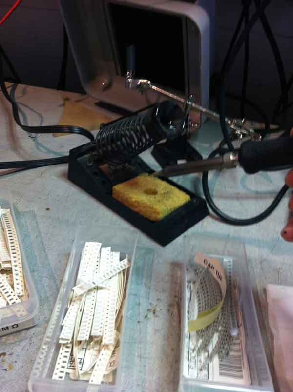
Milling and Soldering
At the beginning, I milled a circuit board using the modela(MDX-20).
Then I soldered some parts to the board.
Using Parts
- ATTiny45A * 1
- 6 pin header * 1
- 4 pin header * 1
- 3-Terminal regulator * 1(5V)
- RGBLED * 1
- Resister 10K * 1
- Resister 1K * 2
- Resister 499 * 1
- Capacitor 1uF * 1
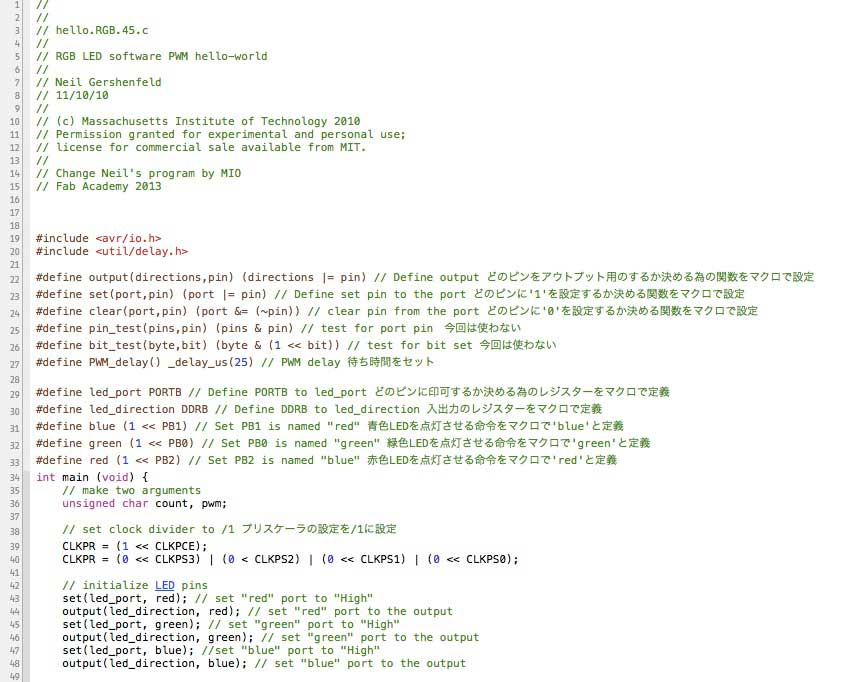
Test
I tested this board using the Neil's code.
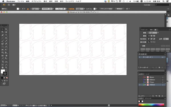
Design
Then I designed the Light cover using the Illustrator.
This design is named IQLight.
I downloaded this design and modified.
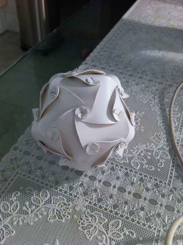
After I designed, I cut it using the Laser Cutter.
Then I assembled it.
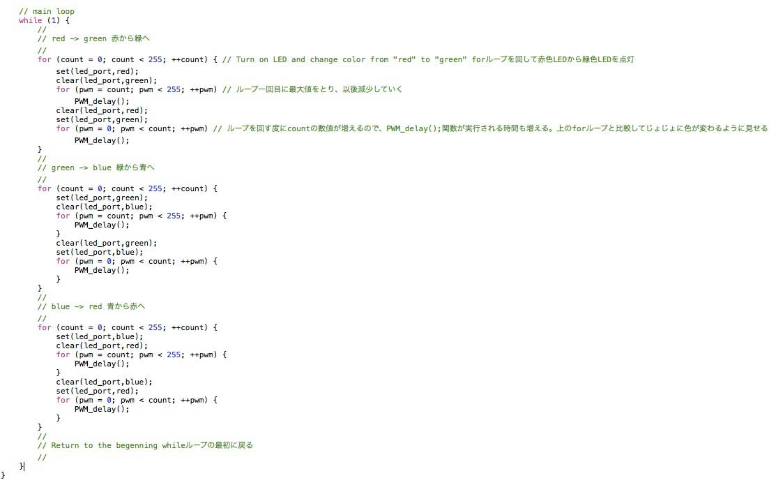
Coding
Then I modified C-code something like that.
Finish
I inserted the RGBLED board into the module.
And Turn on the battery.