


- HOME
- SESSION 2
- SESSION 3
- SESSION 4
- SESSION 5
- SESSION 6
- SESSION 7
- SESSION 8
- SESSION 9
- SESSION 10
- SESSION 11


→ Coimbra, 23 January 2013. Principles and Practices - Project Management
The first day of classes went well. nice to meet classmates and all went well, except the streaming of the videoconference. We traded some ideas wich was great.
Our Project started to get some shape!
I Started to work with mercurial and tried to install it in windows. After some experiences i've sucessfully did it! I'm starting to get familiar with MIT plattform.
I've planned a semester project, wich consists in a modular cd case with electronic control, that is going to support my own audiotheque. I pretend to develope it in the course of the semester, and i'll try to apply the learned modules to the project:
computer-controlled cutting - make the cd cases and pressfits
electronics production - Start creating the PCB board for my Organizer to control the servo motor and the cd labels.
3D scanning and printing - Try to print the modular joints for the cd cases and simulate the servo motor animation.
electronics design - Design my board circuit.
molding and casting - I'll try to use this skill by creating the base for my cd cases.
embedded programming - Program my XX Organizer board.
computer-controlled machining <- No need to make something big
input devices - Learn about sensors, specially image processing.
composites - No need to use composites
interface and application programming - Try to create a local interface to control my audio library in XX Organizer
output devices - Learn about sensors, specially servo motors.
networking and communications - try to implement a web application for my project
You can see my semester project inthis video.
This is My first Assignement. Hope you like my site!
Tools Used - Dreamweaver, JavaScript, Adobe Photoshop CS6, Illustrator
- HOME
- SESSION 1
- SESSION 3
- SESSION 4
- SESSION 5
- SESSION 6
- SESSION 7
- SESSION 8
- SESSION 9
- SESSION 10
- SESSION 11


→ Coimbra, 30 January 2013 - Computer-Aided Design
Inspite of the problems getting a connection through Linphone, the class went well, we've talked about our projects and other issues and challenges. We are starting to work together as a team. We've discussed about new ways of watching the class and avoiding these continuous risks. We have come to an agreement and shared with our sponsors in Fablab.
After the class i started to think about my project wich you can view the entire evolution in this video (My animation is at the final seconds).
Tools Used - 3D Studio Max, V-Ray, Windows Live Movie Maker, Adobe Photoshop CS6, Illustrator, Autodesk Autocad
- HOME
- SESSION 1
- SESSION 2
- SESSION 4
- SESSION 5
- SESSION 6
- SESSION 7
- SESSION 8
- SESSION 9
- SESSION 10
- SESSION 11


→ Coimbra, 6 February 2013 - Computer-Controlled Cutting
Another lesson without good signal, unfortunatelly it's starting to become usual. We talked about our works, started some brainstormings about software, laser cutter and watched some of the latest works in Fablab Coimbra. Also Discussed about the best ways to do 2d, i personally use illustrator and hope keep doing it.
We've worked together in the friday Lab session and started to build a modular box. We used inventor, exported to dwg format, created some 2d views,and stardet to make laser cutting. (View the 3d Animation).
Here Are some Photos of the work done
Due to some problems we had with getting some parts for welding and milling the PCB (some inventory components that are arriving and we didn't have in Coimbra), our sponsor at FabLab Coimbra, José Viana advised us to make our own pressfit.So i started the creation process and think of anything like a cherry lamp. but then it occur to me a better way, a wood brain teaser. After creating the plan in illustrator i had a problem the pieces are 3d. so a make a 2d plan of every piece (the upper and down part) and started cutting. Here's the final pieces. After that i joined the parts and assembled the brainteaser. Take a look!
Tools Used - 3D Studio Max, Illustrator, Fab Modules, Laser cutter, Vinyl cutter, Milling Machine, Inventor
- HOME
- SESSION 1
- SESSION 2
- SESSION 3
- SESSION 5
- SESSION 6
- SESSION 7
- SESSION 8
- SESSION 9
- SESSION 10
- SESSION 11


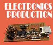
→ 13 February 2013, Coimbra - Electronics Production
After watching the class, we get the idea and started to make our new assignment. We modelled tha board and had a little theoric and practic class about welding. We didn't have the correct pieces for the modella machine so we had some problems with cutting the pcb.
We Had some problems using the FabModules, because Ubuntu was running through Virtual Box. We had also Luciano Betoldi's help but unfortunatelly the machine kept malfunctioning. Finally the components arrived and we started solding the already done pcb, it was a minucious process but it felt good with the final result.
Next step was making the 6 Pin cable to start programming, it was a very intuitive process, as you can see in the photos
Then i started the flashing process by downloading the firmware files and opening ubuntu. Then i edited the makefile file and choosed usbtiny for connecting. then i process the commands above:
make hex
make fuse
make program
And some errors occured with hg fuse. I decided to take a look at the board and detected a double welding in the microcontroller pins
After that i suceeded the connection and
Here's the text file to prove it!
Next step is to make a press fit for my FabISP!
Tools Used - Modella resident software, Solder, solding fluid, desolder, Illustrator, Fab Modules, Laser cutter, Vinyl cutter, Milling Machine
- HOME
- SESSION 1
- SESSION 2
- SESSION 3
- SESSION 4
- SESSION 6
- SESSION 7
- SESSION 8
- SESSION 9
- SESSION 10
- SESSION 11


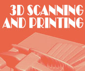
→ 20 February 2013, Coimbra - 3D Scanning and Printing.
This was a productive LabClas. Inspite of still not having the components and PCB we started to do 3d scanning in the modella machine.After a few adjustements the machine started to give nice results, but the time spent on scanning growed significantly. I'm a geocacher and i have some travel bugs so i decided to scan one of my TB's
It's a chair and that's how the scan looked like, exported as a stl file.
In the meanwhile, as the assignement was creating my own 3s scanner i searched on the web and found this video that explaind how to create one. After a few tests we started to have better results (tried to scan a chess piece)
The mesh edition process was initiated in 3d studio max, and did some weldings, smoothings, normals .Then i tried other software as MeshLab , netfabb, and meshmixer. For mesh edition meshmixer was the best for me, but Meshlab proved to be very eficient in the cleaning/ repairing process. This part was important for me to know those tools and get my own way for working in these area. After the mesh editing i sent the final 3d model to the 3d printer at our Fablab, the Uprint.
This is how it printed my scanned model.
.
- HOME
- SESSION 1
- SESSION 2
- SESSION 3
- SESSION 4
- SESSION 5
- SESSION 7
- SESSION 8
- SESSION 9
- SESSION 10
- SESSION 11


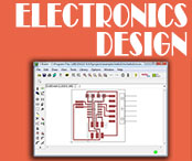
→ 27 February 2013, Coimbra - Electronics design.
First of all, Thanks to Anne France for his great tutorial
Started to download and install Eagle and its fab librays. downloaded the Board Hello Echo and Schematic and read a lot about this area wich i confess it's a bit weak.
I stated work with eagle and it become clearer and clearer as i advanced by the tutorial. I didn't realize i was making my own board by my own way . Then i exported to png ande edited in photoshop by inverting the collours and adding some text and it worked like this.
A Week Later the milling tools arrived and we started to work properly We used this milling drill and it worked perfectly. See the final result here.
Next session we started to weld the components and it didn't run so well, and i think it was because i used a bit more welding fluid thank i should, the board heated and some copper lines detached from the board. I had to make a jumper to connect the 6-pin programming header and the 10k Resistor, and in the end the circuit seem to work. I Used the multimeter to check the weldings and the tracks and everything was connected properly.
Here are some pictures.
Tools Used -DR Picza, Eagle, Photoshop
- HOME
- SESSION 1
- SESSION 2
- SESSION 3
- SESSION 4
- SESSION 5
- SESSION 6
- SESSION 8
- SESSION 9
- SESSION 10
- SESSION 11


→ 6 March 2013, Coimbra - Molding and Casting.
We are still waiting for the components to arrive at fabLab. Serious dificulties with getting the material on time at the Lab.
I started to think about what i would make and i decided to mold one of my favourite dogs, wich i own, scottish terrier, called Anis.
I got a picture of my dog and started editing in illustrator to vectorize it, both the superior and inferior mold. I don't need the negative mold because my shape is simple, has only an eye on the superior mold. I modelled on 3d studio max and this was how it went.
Finally i got some renders, as you can see here.
Then i started to work with the modela. We used paraphine boards to mill and it looked like this. i used the 0.8mm mill with the definition in this photo.
I decided not to make the finishing process and i didn't regret because the paraphine was percect. I just retouched it with a little screwdriver.
Then the resine composing started. After reading the security instrucions, i put a pair of gloves and start mixing the liquid rubber for making the negative mold.
Here are some photos:


I had to wait for a week to come back and get the negative mold dry and ready to receive the transparent plastic. I filled the negative mold wit it and waited aprox. 1:30 hour. Here's the final result:


I'm preparing some chocolat scottish for the Easter, Will show you later.
Tools Used -Photoshop, web, Illustrator, 3d studio max with Vray
- HOME
- SESSION 1
- SESSION 2
- SESSION 3
- SESSION 4
- SESSION 5
- SESSION 6
- SESSION 7
- SESSION 9
- SESSION 10
- SESSION 11


→ 14 March 2013, Coimbra - Embedded Programming.
After reading some electronics tutorials we started by building the FDTI cable and the6 PIN cable. I connected the Fabisp and followed Anne Kaziuna's tutorial, in windows environment. I downloaded arduino 1.0.4, fabisp and tinyusb windows drivers and started the bootloader process after configuring the com ports, the clock speed and the arduino programmer(FABISP). Everything went well and the bootloader was sucessfull.
After that i opened the button sample program in the arduino librarys and tested it . I only had to change the controller ports for the led and the button and it went well. I was so excited that i forgot to take pictures and document the whole process.
The program run as expected, but then the problems started. I changed the program to invert the led actions:
if (buttonState == HIGH) {
// turn LED off:
digitalWrite(ledPin, LOW);
}
else {
// turn LED on:
digitalWrite(ledPin, HIGH);
And there were no changes. I then used the delay command for the blinking LED:
digitalWrite(led, HIGH);
delay(1000);
digitalWrite(led, LOW);
delay(1000);
The compiling and uploading process went fine (blinking LED, Hello ECHO), but after that it kept doing the same instructions (LED ON, button turn LED OFF). We started to discuss about finding the problem, and it seems it has something to do with the replacement of the 20 MHZ resonator with an oscilator and 2 condensors, wich seem to have the same performance.
Next week i'll try to change the clock frequency to internal and ask for my instructors help, to solve the problems, check all the boards connections and weldings, and run the hello echo program in ubuntu environment.
Here are some pictures of the entire process.
Tools Used -AvrDude, Arduino 1.0.4, notepad++ on windows plattform
- HOME
- SESSION 1
- SESSION 2
- SESSION 3
- SESSION 4
- SESSION 5
- SESSION 6
- SESSION 7
- SESSION 8
- SESSION 10
- SESSION 11


→ 20 March 2013, Coimbra - Computer Controlled Machining.
We are having problems with the CNC rouuter in Fablab Coimbra, because it's been built by root and things haven't run as expected. Because of this we started to think about what to do, and try to make it in the Laser Cutter. I'm going to make a geocache for an Institution here in Fundão, and it's going to look like a cryptex. I'm still modelling the concept to get the result i want and hope to get the final cache soon.
Toni concepted a fireplace chair and we started together to cut the chair. The purpose of this chair is to create something big later, and joint the chairs to transform it into a garden chair. Here are some photos of the done job:


Work done! I'll post later my geocache project.
Tools Used -DR Picza, Eagle, Photoshop
- HOME
- SESSION 1
- SESSION 2
- SESSION 3
- SESSION 4
- SESSION 5
- SESSION 6
- SESSION 7
- SESSION 8
- SESSION 9
- SESSION 11


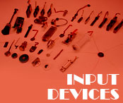
→ 27 March 2013, Coimbra - Input devices.
24-03-2013
At this point we are wainting for the sensors to arrive and depending on the type of the sensors we will mill the corresponding board and weld the correspondent components. I've bought some electronic stuff to practice some electronics and improve my knowledge while i'm not at the Lab sessions. more info coming soon.
07-04-2013
When the components arrived, we decided that each one of us would make a diferent board, and i got the sound challenge, tha microboard. We started cutting our PCB's at the modela with the 1/8 milling drill. We updated the milling speed to 4mm/s and it became really faster without breaking the drill. In one hour we milled and cutted all the fablab student boards.
So then we started to collect the components.
I then started to weld the components in the board with Toni's help, who's got good welding skills. Here are some pictures of the board:


Hoping to program my mic board in the next lab session, because my ISP insn't connecting anymore, something went wrong with the circuit and i still didn't figure out what it is. Maybe i'll program it again, maybe i'll ask for my instructors help. Otherwise i'll have to make another FabISP or use one of my classmates.
15-04-2013
I've finally get to connect, after installing all the dependencies, downloading the C file the Makefile, and the PY code just typed:
sudo make -f hello.mic.45.make program-usbtiny
it flashed correctly
avr-objcopy -j .text -O ihex hello.mic.45.out hello.mic.45.c.hex;\
avr-size --mcu=attiny45 --format=avr hello.mic.45.out
AVR Memory Usage
----------------
Device: attiny45
Program: 500 bytes (12.2% Full)
(.text + .data + .bootloader)
Data: 200 bytes (78.1% Full)
(.data + .bss + .noinit)
avrdude -p t45 -P usb -c usbtiny -U flash:w:hello.mic.45.c.hex
avrdude: AVR device initialized and ready to accept instructions
Reading | ################################################## | 100% 0.00s
avrdude: Device signature = 0x1e9206
avrdude: NOTE: FLASH memory has been specified, an erase cycle will be performed
To disable this feature, specify the -D option.
avrdude: erasing chip
avrdude: reading input file "hello.mic.45.c.hex"
avrdude: input file hello.mic.45.c.hex auto detected as Intel Hex
avrdude: writing flash (500 bytes):
Writing | ################################################## | 100% 0.87s
avrdude: 500 bytes of flash written
avrdude: verifying flash memory against hello.mic.45.c.hex:
avrdude: load data flash data from input file hello.mic.45.c.hex:
avrdude: input file hello.mic.45.c.hex auto detected as Intel Hex
avrdude: input file hello.mic.45.c.hex contains 500 bytes
avrdude: reading on-chip flash data:
Reading | ################################################## | 100% 1.00s
avrdude: verifying ...
avrdude: 500 bytes of flash verified
avrdude: safemode: Fuses OK
avrdude done. Thank you.
After that i checked my usb port by typing:
ls /dev/tty.usb*
then typed
python hello.mic.45.py /dev/ttyUSB0
and it worked perfectly as you can see in this video. WORK DONE!
Tools Used - Photoshop, Eagle, Fab Modules, Modella Milling Machine, Ubuntu 12.04
- HOME
- SESSION 1
- SESSION 2
- SESSION 3
- SESSION 4
- SESSION 5
- SESSION 6
- SESSION 7
- SESSION 8
- SESSION 9
- SESSION 10


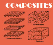
→ 3 April 2013, Coimbra - Composites.
At this point i am thinking what kind of mold to make, to start modelling it in 3d. I hope to see Neil's class better to understant this concept. I'm afraid that there aren't components for this assignement at Fablab Coimbra.
14-04-2013
I've decided to make a dock station for my phone and i started modelling in 3d Studio as you can see in the above pictures:


Next lab session i will mill the mold at the modella machine and use resine with glass fiber to make the docking station. I saw tha class and fabacademy students wich inspired me. Thanks for that! hope to show it here next week.
Tools Used - 3d Studio Max