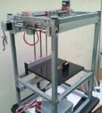
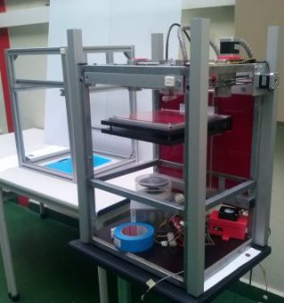
I began to design and build the machine assembled using galvanized steel structure but there were some issues with this choice. The 2 stepper motors used to drive Y axis movements were designed to became outside of the the main frame and it can be a problem, they are too exposed and it is a major problem to cover the machine. With the difficulty to drill the steel structure, so many times needed after assembly, I decided to assemble an aluminum frame using bosch rexroth profiles. With the difficulty to drill the steel structure, so many times needed even after assembly, I decided to assemble an aluminum frame using bosch rexroth profiles. With that new frame it is much easier to connect any part or mechanism on the structure.
Working on CAD 3D (Autodesk Inventor)
CAD details are very useful to check if everything is ok. Afterwards they are useful when it is necessary to assemble all the parts together. Each part approved in CAD that has to be machined with digital process fabrication must be exported in a 3d format or in a 2d format depending on the machining process to use.
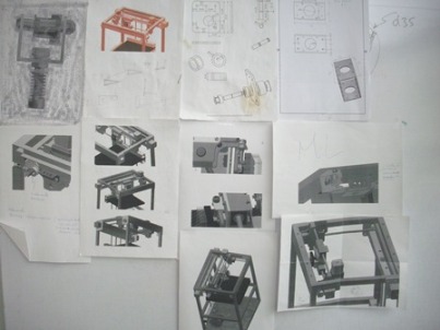
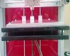
A working wall is very usefull because we take both details and global visualization of the project, we can make a working wall from a card board or something more rigid.
Innovations:
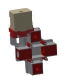
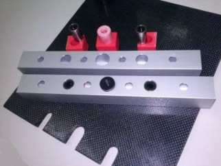
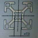
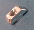
1 - 3d printing cubes inside of Aluminum square tubes, these set holds the shafts (axis), allowing quick alignment between parallel axis, and the assembly or disassembly is very easy because they don't have screws connected (provisional patent application Nº20141000060128, submitted in Portugal).
ABS cube can moves inside aluminum profile just in one direction (horizontally at the image). Plastic parts perfectly adjusted inside of aluminum works fine for this purpose. These cubes are for holding the shafts although they allowing manual alignment or auto-alignment of the shafts when machine works.
Additionally, it's very simple to assemble/disassemble all the shafts, very useful for maintenance operations (please, see next video).
Video (Assembly/disassembly shafts)
Innovations:
2 - Compact set for filament traction and extrusion (provisional patent application Nº20141000060526 submitted in Portugal for an improved model)
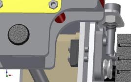
The filament traction mechanism has 19 parts and allows very efficient traction of the ABS (1.75 mm) filament, has adjustable compression force trough a helical spring (with adjustable screw) and allows very easy change of filament. I used two precision hand made bushings (steel) to improve lever action (it works so good that I have afraid to make another one). The major parts are made in aluminum, I machined the first components in Ouplan CNC Router (Fablab Aldeias do Xisto, thanks João, Tony, Nuno, Ivan).
Figure above also shows the belt holder that provides the traction of entire bridge (gantry), performing the displacement of the extruder in Y direction (2 motors are used, one on each side) .
Machining parts in Fablab Aldeias do Xisto
Some acquired parts (necessary to make extrusion system works): 100K thermistor, thermal tube, v groove bearing, mk7 aluminum thermal core (we may machining one of this), filament drive, cartridge heater 12v 40w, and helical spring of course. The tip can be seen on the right side (gas jet nozzle for cookers or heaters). I have used pc mouse switches for endstops (Put at X min, Y max, and Z max).
Global view of the build plate set (heatbed MK2 and tempered glass 3 mm height on top, shafts/guides of 8 mm diameter for axis (X, Y, and Z), extruder set with heatsink and fan).
Details of build plate construction on right side of this page (and in composites index).
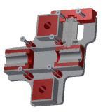
Next it's shown the development of subsets/holders for linear bearings used for moving gantry in Y axis. Simultaneously both headers holds X shats and provide sliding of the extruder through X axis.
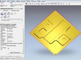
CAD models (section views of hubs assembly), and final assembled parts.
The same process used to plate sliding trough Z axis, was implemented here (X and Y movements). Firstly I went to CAD software to design all the parts and, after modeling parts assembly, proceed with testing functionality, after that, exported the stl files and went to artcam for generating g-codes. Finally I used the CNC Router to cut the parts.
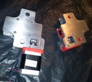
I have used M3 screws to link the major parts of moving sets. On the right side of the page we can see the machining process of side covers that holds and tights the linear hubs. These side covers holds and tights the shafts ( X axis) at their ends, through ABS blocks assembled inner aluminum cubes.
Picture above shows the assembled aluminium parts and ABS parts (missing the linear bearings inside ABS cubes). These headers, used for Y movement, when completely assembled and linked together they form a bridge. They are also used for controlling X-Axis. We can see, from the picture on right side, the motor that will be attached to this side header. When it works the entire extrusion mechanism is pulled and moves trough X axis.
Each side of the machine has a drive motor (stepper motor) in one side and a freewheel in the other side linked by a belt. So there are traction on both sides of the 3d printer moving the Y axis.
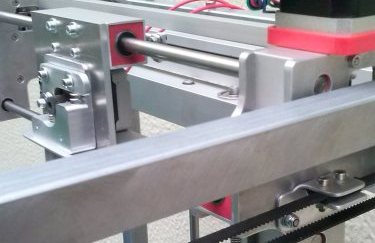
The next images shows the 3 Axis with the assembled parts. Also used a beam (bridge) made of square profile of aluminum visible in the photo. This beam can keep distance between headers when they tend to rotate around Y axis due to the traction force caused by the belt of the X axis.
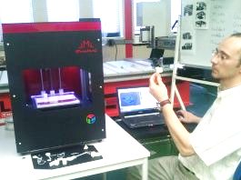
I took the bridge to glue a strip of LEDs below the bridge.
For tensioning de X-axis belt I found this solution:
This set of two helical springs works very nice for tensioning the X axis belt.
Detail of the Y axis belt attachement in the headers.
Innovations:
3 - Freewheel pulley for tensioning the belt and for providing misalignment compensation when the belt isn´t perfectly oriented with both pulleys (motor and freewheel). This mechanism was submitted in Portugal as a provisional patent application Nº20141000060492. The set contains 18 parts and allows pre-tension regulation of the belt. It can make small angular movements for compensation of belt misalignments. In adition, It allows the change of the belts becames a very easy operation.
Belt connections (freewheel plus header).
The three connections of the belt.
The Y axis is drived by 2 twins sets of these ones, so we must pay attention when wiring the 2 stepper motors to drivers (one inverted).
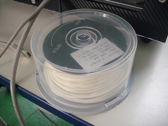
Look the solution that I found for ABS filament cartridge. Externally it's a CD/DVD box (made a little hole to pass the filament). Internally it's a spool that was been used in mig welding. They work so fine and if we put a little silica gel bag on the top of the spool practically there is no humidity contamination.
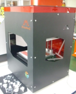
Covers
The covers are made from acrylic and vinyl (textured carbon fiber). At this stage, all the tasks were realized in FabLab Guarda (waiting for some renovation work to be done in the space). I used the Epilog-Helix to work the acrylic and the plotter GX-24 to cut the vinyl.
Top cover, aluminum square tubes, acrylic and vinyl.
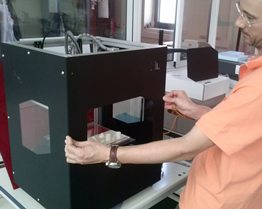
sorry, I didn't took many pictures about this specific task. Actually I thought that would left the machine naked, but after saw it working so well that I went for making a box to cover it. And it took much time to design and build all the covers.
Electronics
Have used a sanguinololu rev 1.3b, 4 stepper drivers and 5 motors.
Y axis drives 2 motors, so I had to make a parallel (derived) circuit to wiring them in the same plug and had to invert one connection because these motors are positioned one in the left side and the other in the right side of the machine head.
In second image above we can see, from the left to the right, one 4-way male pin-headers plugged to X motor, another to Y (double) motor, another to Z motor and further more to Extruder motor. Each 4-way colored cable goes to relative stepper motor.
Wiring need to be arranged.
Note the red ABS box that contains the electronics is ventilated by a system PC fan (recycled, and not visible from the inside). The blue box visible in the two images above was availed just for tests.
I have used a 12 V car relay and a 15 A fuse to power the heatbed (controlled by sanguinololu). I know that I'm using double protection because there is a MOSFET on the PCB to do this task, I do it just to avoid that about 12 A pass through PCB and also to hear the on/off noise in this test stage.
I have been used two sleeve made of fiber glass to separate and insulate the thermistors wires (for the tip and bed). Externally, to hold the insulated wires have used aluminum tape. Some vendors of electrical material have holders for halogen lamps that use fiber glass to insulate the wires, so, I took these sleeves and used them.
Electronics/software
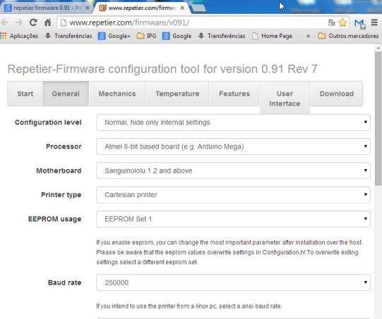
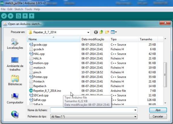
I had to decide between Marlin, pronterface, cura and repetier, and because repetier is so much used and "easy" to find information about it than I have worked with Repetier. So, after installed Repetier Host in my "Ultrabook" I went to Arduino to stablish connection with my new 3d printer. But before that, I went to www.repetier.com/firmware/v091 (firware configuration tool) and I had to configure my initial file to be loaded later in sanguinololu through the Arduino.
Firmware configuration to be loaded in Arduino, so more accurate changes may be done later (configuration.h file opened in arduino), and after that we may upload it into the machine.
With Arduino I changed, in the Configuration file, the necessary data to match better the electronics and the physical things (dimensions, location of endstops, etc.). It was absolutely necessary to adjust other parameters, like axis and extrusion speed, temperatures of extrusion, etc.. Latter, when I installed the heatbed, I had to adjust the best temperature of it (worked with ABS)...but all of this work can be written on dozens of pages and unfortunately my English is really poor to do so timely...(I'm really sorry about my English).
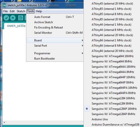
Establishing connection between the main controller of the machine and computer (arduino).
Open the repetier main file (*.ino) in arduino to manipulate it in there.
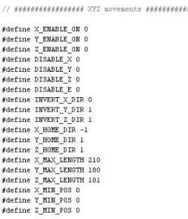
I had to change configuration of ENDSTOP_Y and ENDSTOP_Z because, when I change de structure from galvanized steel to aluminum, I inverted positions of these endstops. Also had to change the Pins.h file because I want to keep the minimum position of the Y axis in front side of the machine and keep the minimum position of the Z axis at up position of the build plate. As I put Y endstop at rear side and Z endstop at down side of build "chamber" I had to invert some definitions to make it work (see endstop and xyz movements configuration on the right side of this page).
Set X, Y, Z and Extruder parameters.
Repetier host has a calculator for axis steps per mm, in this case I have 1.8 deg rotation per step in every motor and have used a 20 teeth pulley in both axis (X and Y). If you calculate by hand don't forget to multiplier x16 (substeps).
Important Note: I had to adjust about 0.38 V in stepper drivers because at values below some motors were losing steps (vibrations and noise).
Working with Repetier and Slic3r
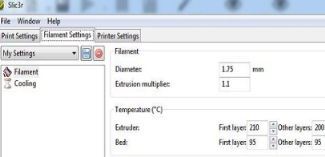
3D Printer configuration within Repetier (sorry, I installed Repetier in Pt).
So many adjustments can be done before generate G-codes from a STL model loaded into Repetier. As a matter of fact, it's Slic3r that allows this feature. We can set almost everything like speeds, accelerations, layers and perimeters mode deposition, etc. So, when Slic3r generates the CNC code these parameters prevails.
Stl model in Repetier.
G-codes generated with Slic3r (working within Repetier).
ABS model detail
The machine prints within 205 mm, 180 mm, 180 mm. Just used ABS 1.75 mm diameter, until now, fused at 200 ºC and have used heatbed at temperature about 95 ºC.
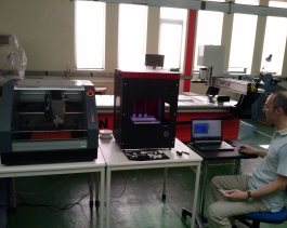
Because the assembly have shown a very good behaviour, I will build a larger volume of build chamber by using the same technics, although reinforcing some components like shafts and linear bearings, of course.
|