For this assignment I chose the light sensor circuit.
The phototransistor can amplify de collector current (Ic) when the base receives light (Ib). The Emitter is conected with ground and the colector pin sends the signal to PB3 (pin 3) of the ATtiny45 (input). The output signal is from PB2 (pin 2) of the microcontroller, conected with terminal Rx (to FTDI cable).
The FTDI cable receive the signal (Rx) and send it to PC USB port.
First we have to program the ATtiny45 to conditioning the light signal and send it to Rx of the FTDI cable.
Then we have to run the python file to show the converted signal in graphical way.
After cutting the circuit board using fabmodules and modela and soldering all the components we have got the sensor of light circuit ready to be programmed.
The assembled circuit with all the components is shown on the right side of the page.
So, Connect the fabISP to an USB port and hello light board to another USB port (via FTDI cable) and let's go to find them in Linux (UBUNTU 12.04).
type: lsusb

with two circuit boards connected and powered (FTDI conected), type:
ls /dev/ttyUSB*

So, in my case, I must to use ttyUSB0
Before run python file, to see the graphical interface, I had to install PYTHON package TKinter. To do so, in terminal, type:
(sudo) apt-get install python-tk
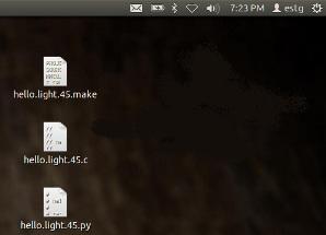
After that, copy the make, c and py files to the desktop and, in terminal:
Move to Desktop:
estg@estg-A7C:~$ cd Desktop
And then, type:
estg@estg-A7C:~/Desktop$ sudo make -f hello.light.45.make program-usbtiny
My result:
[sudo] password for estg:
avr-gcc -mmcu=attiny45 -Wall -Os -DF_CPU=8000000 -I./ -o hello.light.45.out hello.light.45.c
avr-objcopy -O ihex hello.light.45.out hello.light.45.c.hex;\
avr-size --mcu=attiny45 --format=avr hello.light.45.out
AVR Memory Usage
----------------
Device: attiny45
Program: 522 bytes (12.7% Full)
(.text + .data + .bootloader)
Data: 1 bytes (0.4% Full)
(.data + .bss + .noinit)
avrdude -p t45 -P usb -c usbtiny -U flash:w:hello.light.45.c.hex
avrdude: AVR device initialized and ready to accept instructions
Reading | ################################################## | 100% 0.01s
avrdude: Device signature = 0x1e9206
avrdude: NOTE: FLASH memory has been specified, an erase cycle will be performed
To disable this feature, specify the -D option.
avrdude: erasing chip
avrdude: reading input file "hello.light.45.c.hex"
avrdude: input file hello.light.45.c.hex auto detected as Intel Hex
avrdude: writing flash (522 bytes):
Writing | ################################################## | 100% 0.29s
avrdude: 522 bytes of flash written
avrdude: verifying flash memory against hello.light.45.c.hex:
avrdude: load data flash data from input file hello.light.45.c.hex:
avrdude: input file hello.light.45.c.hex auto detected as Intel Hex
avrdude: input file hello.light.45.c.hex contains 522 bytes
avrdude: reading on-chip flash data:
Reading | ################################################## | 100% 0.15s
avrdude: verifying ...
avrdude: 522 bytes of flash verified
avrdude: safemode: Fuses OK
avrdude done. Thank you.
estg@estg-A7C:~/Desktop$
At this point , if want to, we can disconnect FabISP from USB port and ISP conector (hello.light board), because the ATiny is already programmed, so, it just needs the FTDI cable to send data to the computer.
Finally, type:
estg@estg-A7C:~/Desktop$ ( sudo) python hello.light.45.py /dev/ttyUSB0
Now, we can see the graphical response on PC through python, hello.light.45.py file, (video on the right side of the page).
|