Fab Academy
Fab Academy |
Miguel Lourenco |
|||||||||||||||
|
3D Scanning and Printing
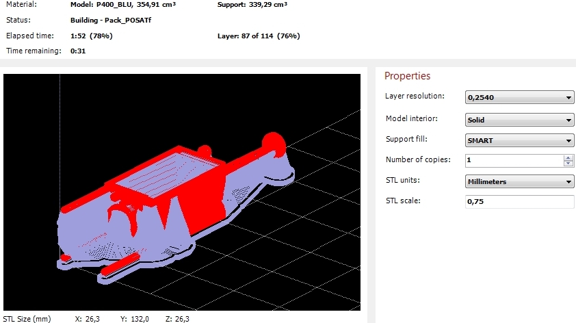
Final 3D printed model.
| ||||||||||||||
3D Scanning |
|||||||||||||||
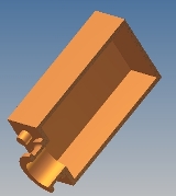
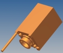
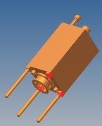
I would like to scanner a PC mouse and after that, edit the resulting IGES or even STL file to modify it and print using another scale. |
|||||||||||||||
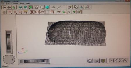
Defining scanning area and pitch (x=1 mm, y= 1 mm) within Dr. Picza – Modela. It would be good if the software allows better defining the scanning volume. It would help to save much time. I was hoping that the process was not so lengthy but was wrong. |
|||||||||||||||
However lower resolution adopted, the “modela” took more than 3h performing scan operations. And I made at least one mistake doing scanning all the volume of the model instead of scanning half of it due its symmetry. When I figured that it was too late and I left the modela to finalize the job. |
|||||||||||||||
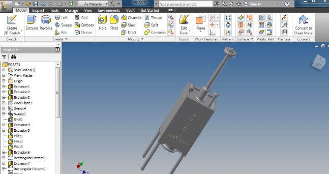
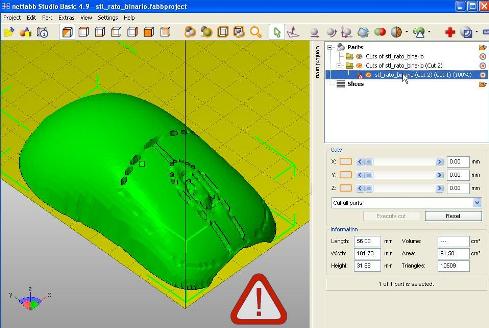
For mesh fixer, begun to open de STL file, exported from modela, in netfabb and used cut tool to trim some protrusions.
As we can see on the right, the model contains errors in its mesh so it is necessary to use repair tools (netfabb). With netfab we can add or remove triangles from the stl file. In my case I did not have missing triangles in the stl mesh. |
|||||||||||||||
After repair the mesh the red/white triangle desappeared meaning that geometry problems are solved and we can save it.
After that, opened it in MesLab and used Filter-Point Set - Surface Reconstruction. Deleted original STL file, resulting a more smooth model. In the MeshLab exported it as a *.OBJ file. |
|||||||||||||||
Have tried meshmixer but did not save the results. I will try it again in the future for sure. |
|||||||||||||||
Finally, returning to netfabb and i had to trim it again, resulting a STL printable solid model.
I figured out that there are so many software applications that can to treat/fix scanning models, specifically, we can fix mesh gaps, get smooth surfaces, reduce complexity, etc, and finaly we can print it. |
|||||||||||||||
|
|||||||||||||||