Networking and Communications Apr 24
In what seems to have become a recurring trend, this week's assignment was to mill some boards, program them, then see if they work. As usual, I had some problems, but overcame them, and was successful.
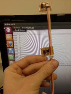
The task this week was networking. I would build a series of boards, and then connect them with a wire so they could send signals to each other. Specifically, I attempted the hello.bus board found on the fab academy. This required me to mill and stuff three boards (at minimum). There would be a bridge board, and then as many nodes as I saw fit. Here are my (final) boards:

I say "(final)" above because a couple of my original nodes didn't work, largely through user error issues. I managed to put the LED on backwards for one of them, and then of course I used that one as a template when stuffing my second one. More on this in a little bit.
After stuffing my original boards, I made a networking wire, and took all three to the computer. I downloaded and ran the hello.bus make file from the fab academy. My three boards were hooked together, and the bridge was connected to the computer and my fabISP. My first attempt left me with this error message:
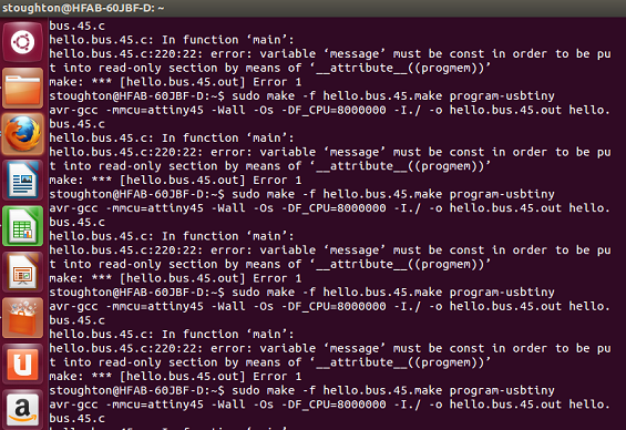
Not being a message I was used to seeing, I had little recourse but to run for help. Anna Kaz helped me out with a new program, and all seemed good in the neighborhood. I flashed the microcontroller, and success on the first (ish) try! I then opened the make file and changed the line #define node_id '0' to #define node_id '1'. I saved, and flashed the microcontroller again. Success! I repeated this process for the #2 and again, success! That was a lot of successes in a row, and I should have gotten suspicious. (Also, if you think I'm a bad documenter because I left out some details there, just wait, the full breadth of my foolishness is coming).
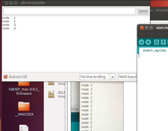
I tried both the Arduino and the terminal programs to get the serial monitor to work so that when I input the board number on my computer, it would light up the corresponding board's LED twice. I got nothing but error messages on my computer, but my colleague Chris said that had to do with the version of linux I was running. My colleague Brad had gotten his to work on his Mac, and offered that I could try. After connecting to the computer, we opened up the arduino, and then opened the serial monitor and hit 0. Nothing happened. I then hit 1. Still nothing and what's that smell? Oh one of my nodes is smoking! It was at this point that we realized the LEDs on my two nodes were on backwards. Both the node boards were fried, so it was back to the soldering board.
It was also at this time I realized a ridiculously silly mistake I had made earlier. When programming the bridge and the nodes, I had not physically moved the fabISP from one board to the next. I had just reprogrammed the bridge from 0 to 1 to 2. When my nodes had been fried, I hadn't even thought to try 2 because 0 and 1 had not worked and what I thought was 2 was on fire. I took the bridge back to Brad's computer, plugged it in, opened the serial monitor in arduino and hit 2. "Node 2" was output and the LED on the board blinked twice! Not all was lost.
I quickly soldered up a couple new nodes, and took them back to program them, this time making sure to move the fabISP each time. I got the usual "Check connections" error once, but by simply ensuring the wiring was a little snugger, that went away. I then took the board to one of our computers with an older version of linux, opened arduino and the serial port and input the numbers 0, 1, and 2. Each lit up their corresponding LED twice (and the others just once).
I even tried to take a video, and I think the remaining challenge of this assignment will be getting that up so everyone can see. If there's a video after this you'll know I was successful.
Look I made a video!