Molding and Casting Mar 6
The task this week was to design a mold using a CAD program, mill the mold, create the actual mold using a rubber material, and then create the mold-based object with a cement-like product. I was channeling my inner 7th grade art student (who has access to expensive milling machines).
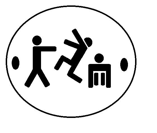
During the lecture for this week, I was inspired by the molded jewelry. I decided to create a pendant that had the logo of my ultimate Frisbee team on it. I wanted the pendant to be subtractive, that is, the actual logo was cut out of the pendant, giving it the color of whatever was behind it. While I stuck with this plan, it did create some problems which had to be overcome later.
I first began by designing the logo in Autodesk. Autodesk has a feature where you can just trace an image, so I inserted a picture, traced, and then extruded on a disk.
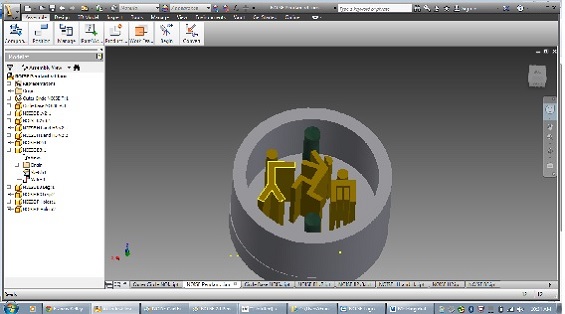
With my still limited experience with Autodesk, I was pretty proud of the product and it took some effort. I realized, however, that if my goal was to have the logo be cut out, that the milled wax had to look like the final product, not like the mold. In order to do this, I had to extrude the image in the negative z direction into a solid cylinder. It took about the same amount of work, but wasn’t any more difficult.

It was at this point that I wondered if there was an easier way to do all this. Turns out there was (sorta). Using the fab modules, and a .png image of the logo, I could simply define the high and low as black and white on the picture, and define the depth on the Modella, and cut it out. I edited the picture in paint to be sure that each pixel was either black or white.
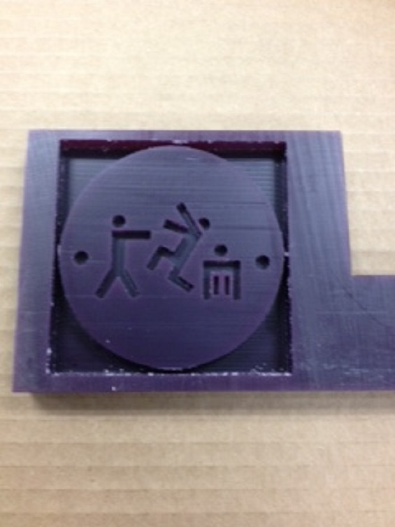
I opened up the Fab Module, imported, changed the bit and specified the depth. Whenever I tried to run it, however, I got an error message. My colleague Brad also could not get it to run (though our colleague Chris had no problems). Pressed for time and not fully understanding the error, I reverted back to the original plan and opened my subtractive CAD file in the milling machine’s software program. The trickiest part was setting the origin and after using some guess and check with the z-axis I was ready to go. On the advice of Brad, what I had originally intended to be a pendant only about an inch in diameter, I increased in size three-fold. This was to ensure enough spacing for the drill bit for the tiny legs on the logo. I hit go and away it went. Final product shown:
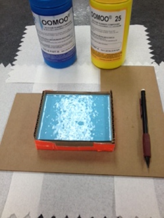
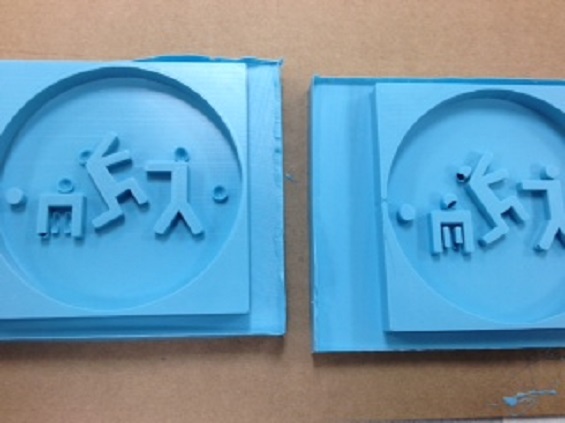
With my wax logo created, it was time to create the mold. I used the OOMOO Tin-Cure Silicone Rubber. It was a pretty simple procedure. Mix the two components, stir, and pour over the model. Not letting my fab-powers make me forget my simple upbringing, I fashioned a case to hold the wax/oomoo out of cardboard and duct tape.
My first attempt had some problems. The bubbles formed in the small spaces of the logo. I also realized upon seeing a draft that this wouldn't actually do what I had intended at the outset. The logo was negatively extruded a different distance than the walls of the disk, as such, the "negative" impression would not actually work. I'd have to re-design and re-mill for a final draft but I'll wait to see how my second attempt comes out.

On the second attempt, I made more of an effort to decrease air bubbles. I specifically applied the rubber directly to the small parts, and pushed the rubber in with a tongue depressor, hoping to squeeze the bubbles out. It turned out better, but still not perfect. In a future attempt, I might try to make those parts bigger in order to decrease the effect of bubbles.
Despite the lack of perfection, I decided to try the liquid plastic anyway. I used the Smooth-Cast 305 from the same folks who did the OOMOO. Mixed it up, poured it in, waited about half an hour. Awesome results shown below.
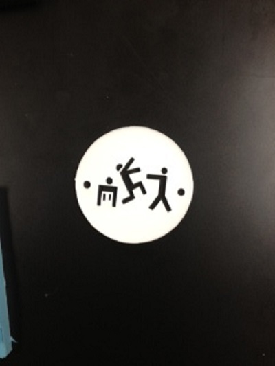
I'm pretty happy with how it turned out. Even though the logo was not as deep as the sides, I was able to pour the plastic only to that height in the mold and it turned out great.
In the future, I would take these steps to make this project better:
1) Clearer understanding of what final product should look like so CAD file matches expectations.
2) Trouble shoot Fab Modules for ease of Modella set up.
3) Manage part sizes to maximize expectations and minimize milling and bubbling complications.