Schematic
-If
you have been following my blog, you would know I'm an
architect who has nothing to do with electronics at
all. it took
me sometime at the beginning it took me a while to
understand circuit basics
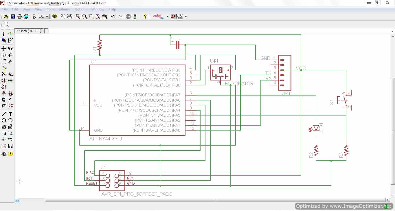
I started adding the components of the circuit one
Schematic Layout on EAGLE software following HELLO
board design
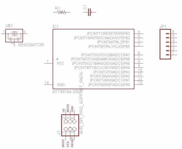
EAGLE the software, allows you to schematically connect
the components you have before converting this to a
board. the
assignment was to add a LED light and a switch to the
HELLO design, a friend advised to add resistors before
each of them
to control the flow of current
 TIP
if you are new to EAGLE
there
TIP
if you are new to EAGLE
there
are tutorials, available
on you-tube are
helpful and easy.
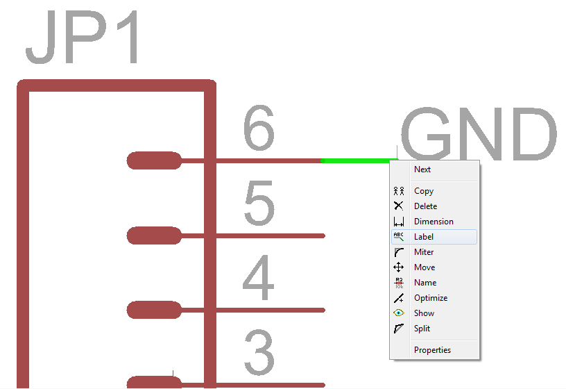
also during working
connections
might get confused as some
of them don't have names so make sure
to re-name and label them to notice
them easily
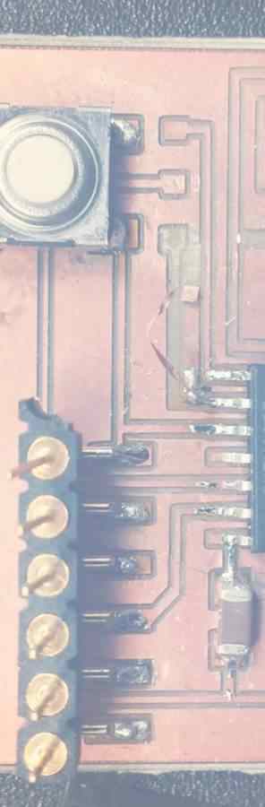
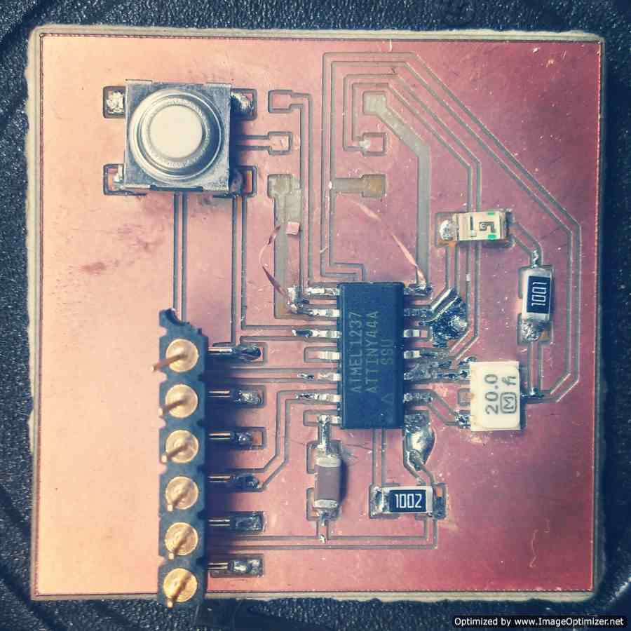
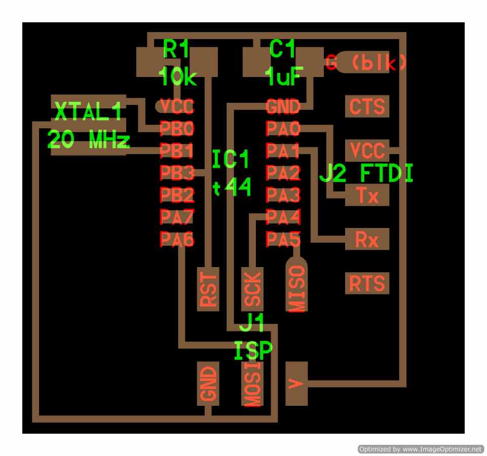
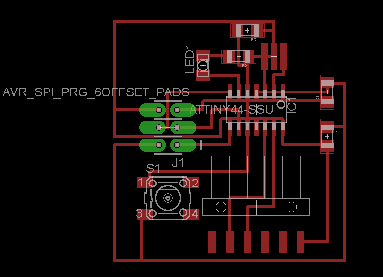
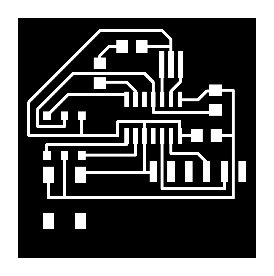
The board
When you convert the schematic
design to a board, it will give you the board with
proposal connections between the components you will
then have to replace them with what's called
"route" where current is supposed to flow
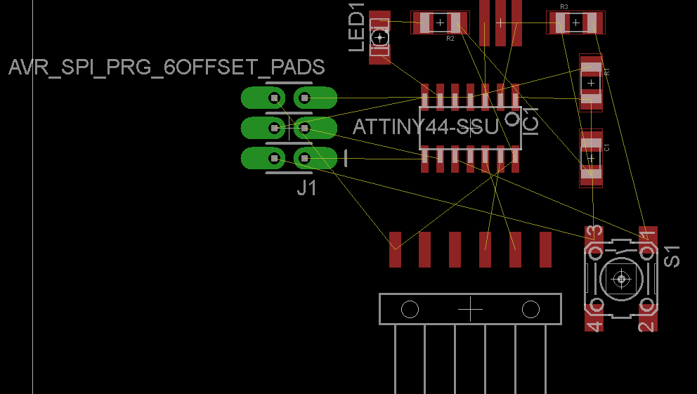
in the beginning it will be chaotic, all the
schematic lines are intersecting. You have to keep
rearranging it so as not to have connections
crossing each others.
Also to avoid having long connections
By clicking on the component the software highlights
all it connections, so you get to connect them one
by one. When you connect them the
schematic connection will disappear. REMEMBER
if you did any mistakes while
connecting you can always click on "rip up",
select the
route and it will convert it back to a schematic
connection
Also if any time you used the wrong component, you
can right click on it and click replace pick the new
one, it will replace it but with the
same connections the previous had, so that you don't
have to do them all over again
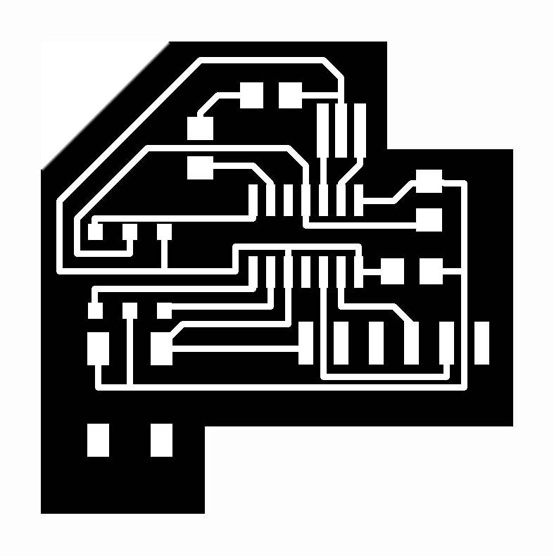
Saving &
Editing
After that go
ahead and save only the top
layer of your design for the
circuit and the dimension
layer for the border as a PNG
image then
start editing the outer
boarder as you wish
for me i used Photoshop its
easier, after i finished
designed the outline i stroke
the boundary with 60PX. Now
its ready for the milling
machine

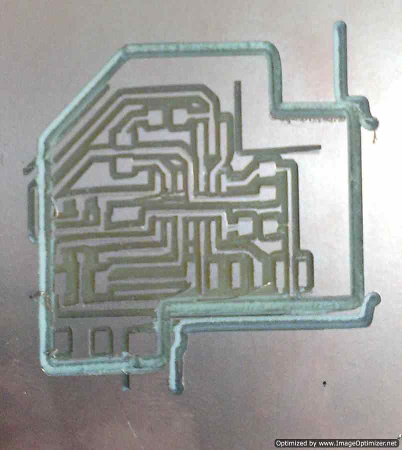 ERROR
make
sure both
ERROR
make
sure both
PNG'S have the
same
(0,0,)
coordinates
otherwise it
prints will
shift
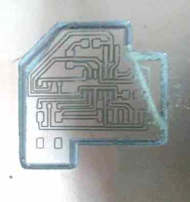
And
out
of
no
where
i had to Redo all
the milling again, so i had a chance so simplify some
of the connections so as the outline,
honestly i don't know what happened to the milling
machine BUT you have to live with it

>Proposal
>Digital model
>Laser Cutting
>Electronic
production
>3D Scanning
& Printing
>Electronic
Design
>Molding & Casting
>Embedded programing
>Computer-controlled
machining
>Input devices
>Composites