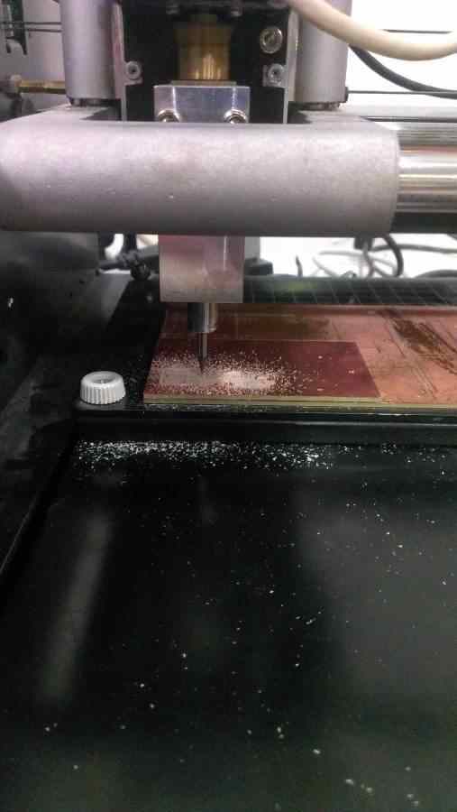
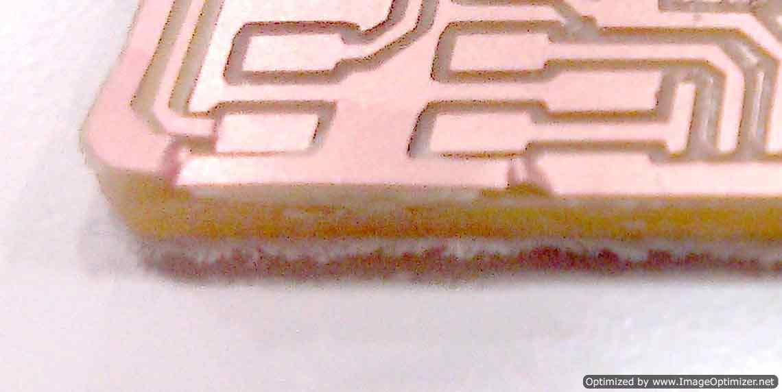
The Milling
-I
wanted it to be directly connected to the computer
through the USB stick
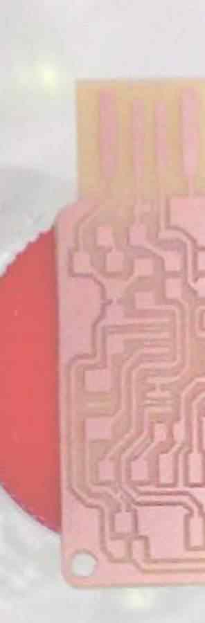
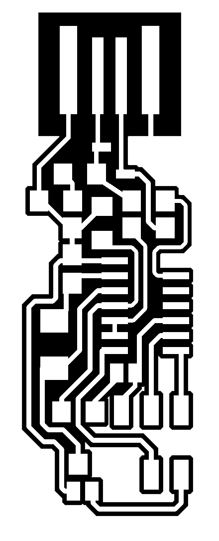
so i downloaded the JPG and the circuit drawing and
started milling the Grey scale
image you see on the milling machine
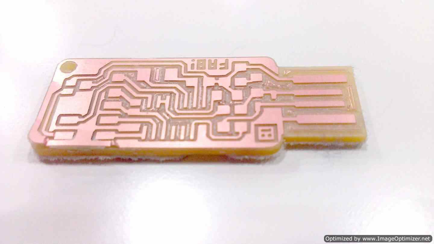
in this case, we used an acrylic board
covered with copper sheet, as the electrical
conductor material,as a body for the circuit.
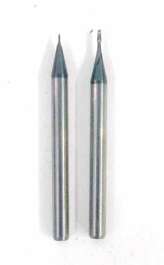
then we used two different pins with
the machine the thick one is to cut the acrylic
board, and the thinner one is for milling
.the circuit itself

while changing the pins you have
to be careful not to fix the pin too low that it
breaks while milling, or too high that it don't mill
with
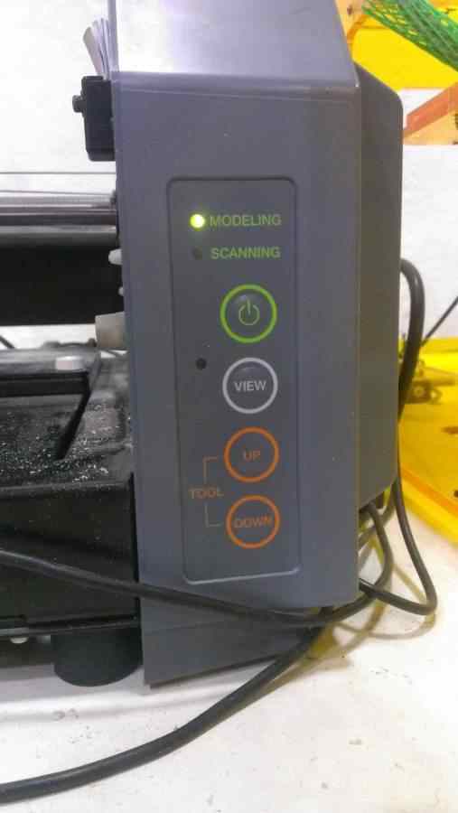
the proper depth. remember
that at any time if you doubted any thing about your
process, you can click VIEW it will pause the milling,
gets you your pad to view it, or adjust the pin's
height and then click view again to proceed
CAUTION
Be
careful while
removing
the
board after
milling,
if you did it
aggressively
it will ruin
the acrylic
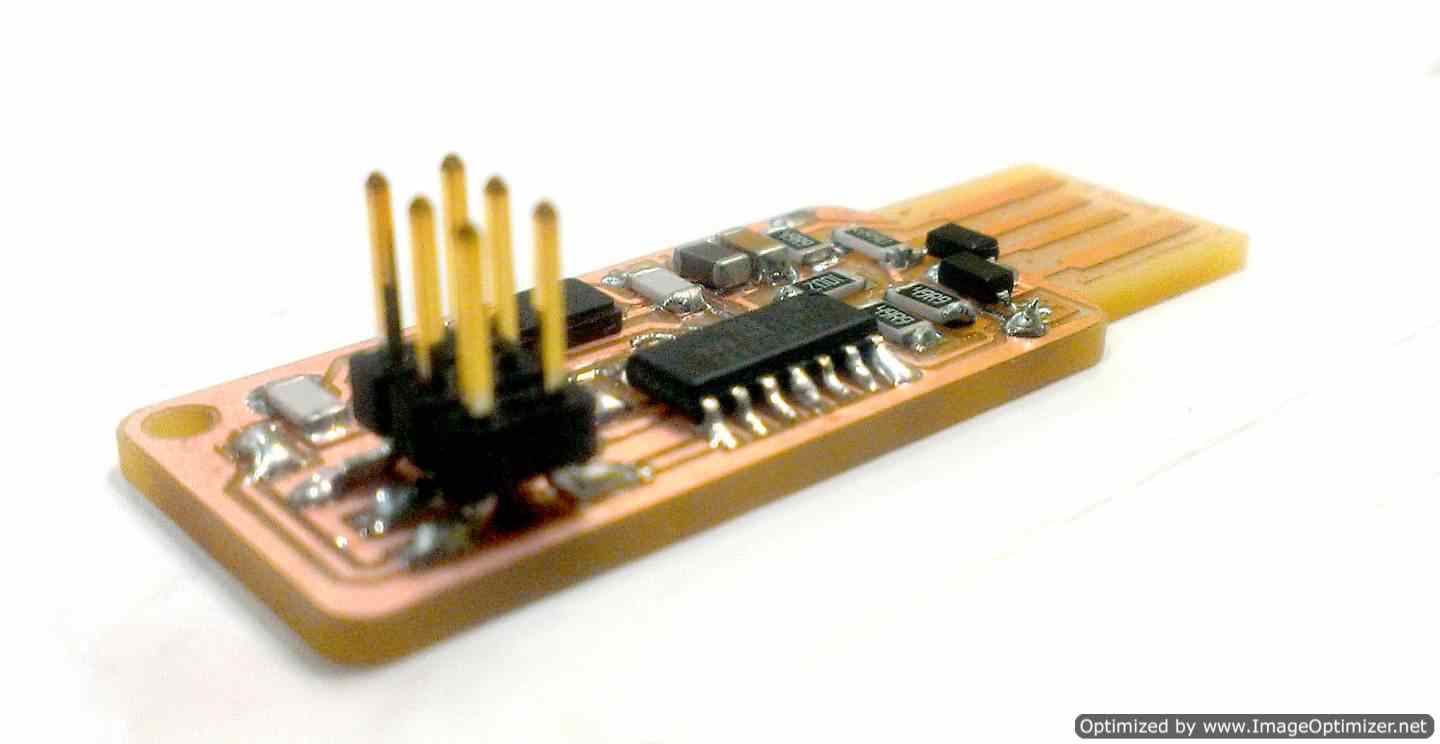
Assembly
-With Photoshop i merged
the circuit's image, with
the
schematic
and assembly drawing.
prepared all the
needed parts and
started
SOLDERING. while
soldering you have to
take care, you don't
heat the wire, you
heat the copper
surface first, then
after 3-4 seconds,
you touch the surface
with the wire. That's
when a little part
will melt. you then
remove the wire and
attract the liquid to
the hot point
before it dries.

-After finishing
you have to make
sure the
soldering
connected the
electrical part
(resistors,
diodes...etc) to
the copper
surface,
not just
physically but
also
electrically, so
you test it with
the
multimeter, if
it made sound,
then the
electricity can
successively
run through,
-
While soldering,
some parts has a
direction,
others don't.
Those who has,
has to be place
exactly with the
direction other
wise they
wont run the
current.
-Sometimes (in
my case) you
need jumpers
between copper
surfaces to
allow the
current between
them. you can do
it in three
ways,
First you can
just add little
part of soldered
liquid between
them, Second way
is to add a
pieces of
uncovered wire,
Third way is to
add a 0 resistor
it will let
current pass
through both
lines without
any resistance
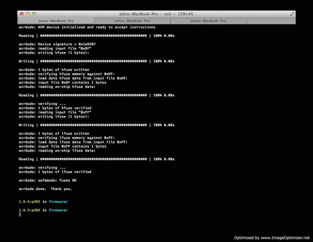
Computing !
-when your
soldering is
done, and
after making
sure with the
multimeter
that the
current can
run through,
you start
programing
with the USBtiny
Programer with
AVRDUDE & GCC you can easily program it !
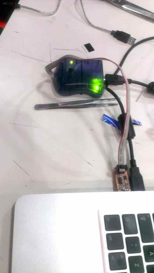
THIS
GREEN LIGHT
MEANS
YOU
ARE
SAFE
NOW !!
>Proposal
>Digital model
>Laser Cutting
>Electronic
production
>3D Scanning
& Printing
>Electronic Design
>Molding & Casting
>Embedded programing
>Computer-controlled
machining
>Input devices
>Composites