-This week i designed
a table out of recycled material got
them from the trash on the heavy
garbage collection day. I fought for a
heavy
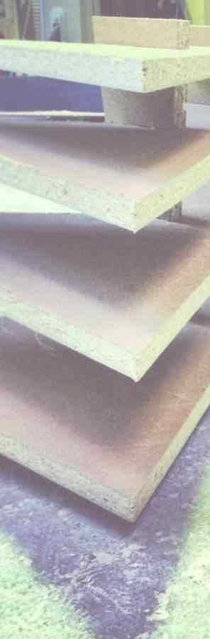
MDF sheet, which didn't suit my first
design, the material was too heavy for
it so i had to change the design to
this one.
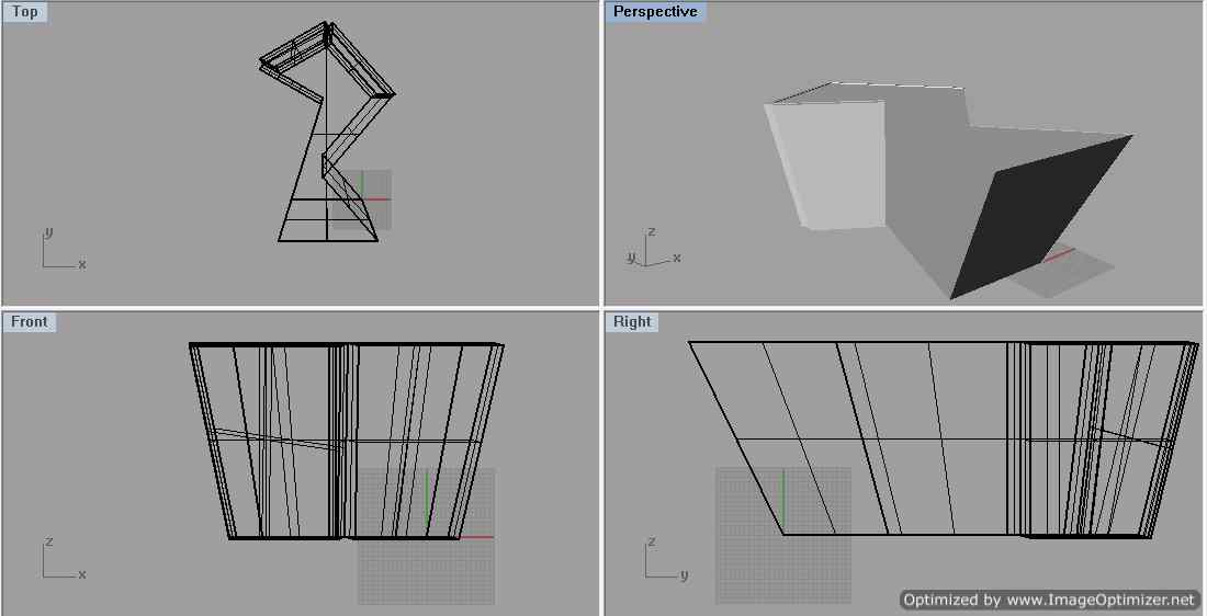
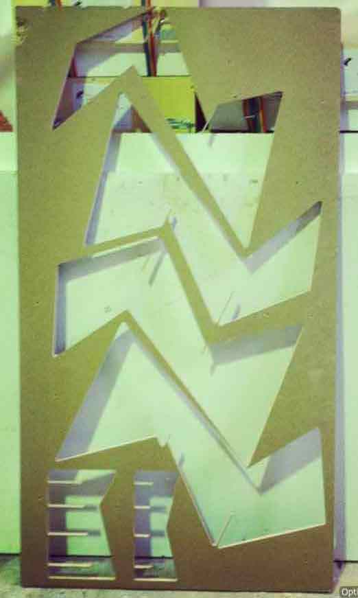
i started the model in RHINO4.0
designing the layout of the mass. Then
with the help of 123D make i managed
to slice it into interlocking
layers.
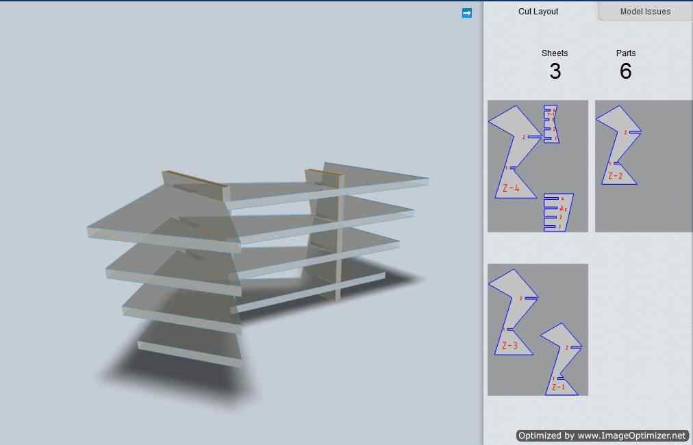
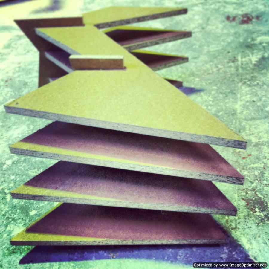
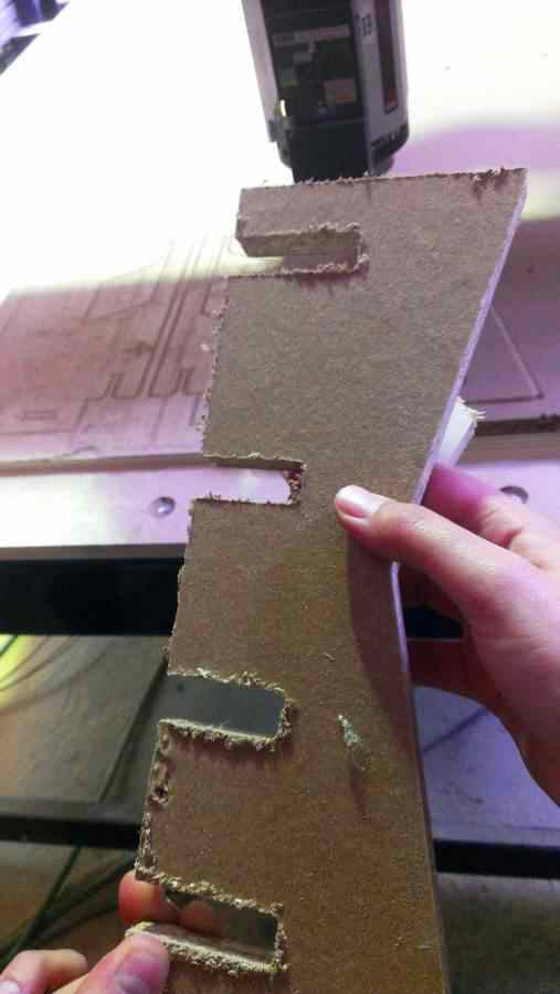
With 123D Make i
managed to slice the mass into 4 horizontal layer which
acts as shelves in my design and two vertical ones which
will be the
supporters. You can rotate the slices or move them on
the 123D make as u wish till your satisfied with the
design, you can also control their
count and control the spacing distance between them if
needed
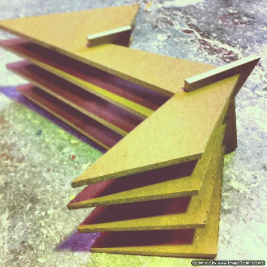
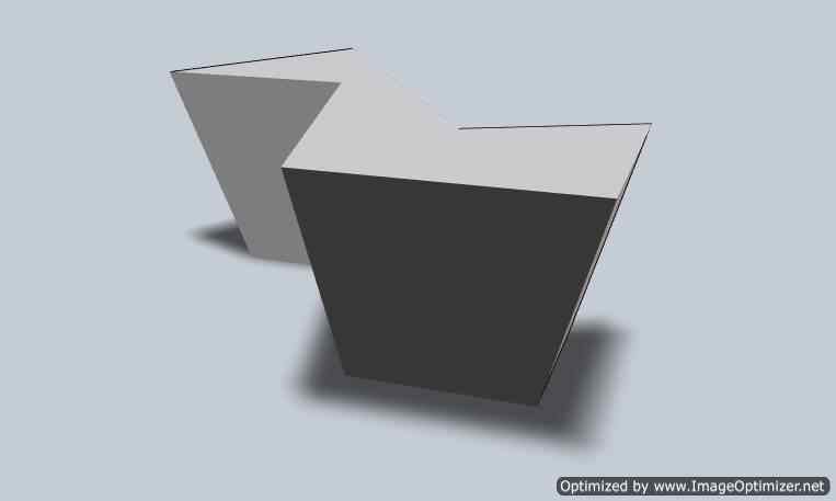
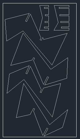
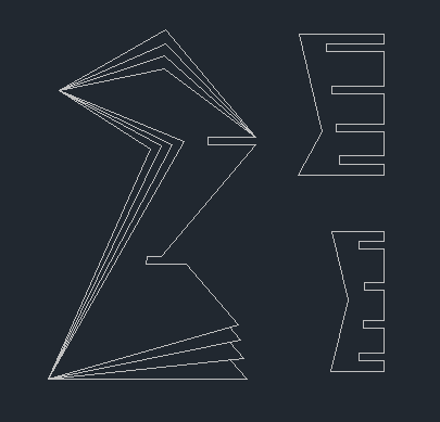
After that i exported the 123D proposal as a DXF i
edited the layout outline of the layers to make the mass
more dynamic, this step is only for
the design in other words i didn't need it, i went for
it only for the final looking mass
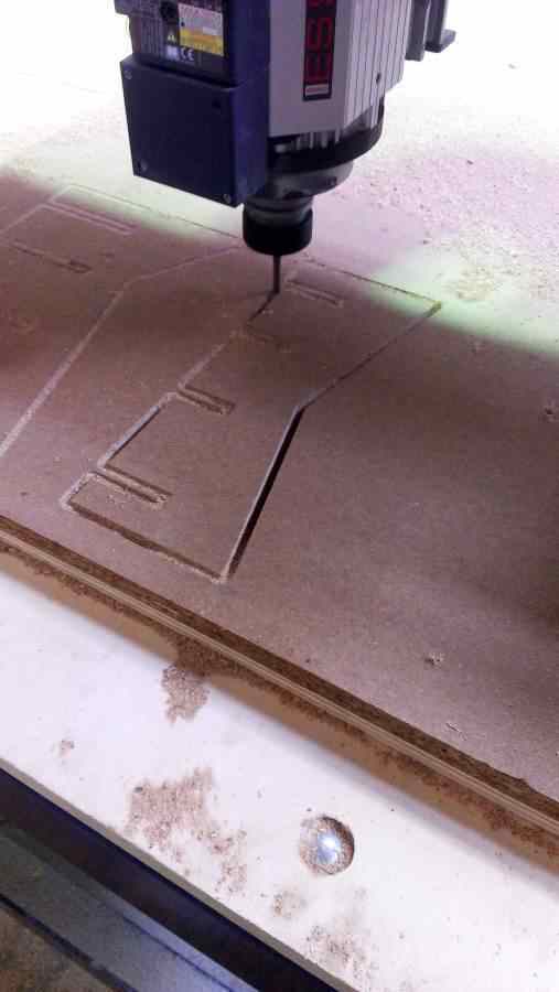
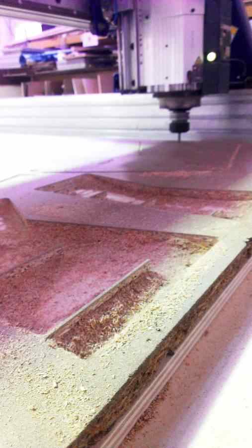
After that came the
machine calibration. Since its a milling machine so it
works with the basics. you have to calibrate XYZ
according to
your file where both the X,Y done manually with
the left and right buttons of the computer while in Z
the machine has to calibrate it
itself using a metal sheet and a sensor by placing this
pad below the pin it keeps on going down till the sensor
feels the pad and it stops,
after that it automatically subtracts the pad's
thickness from the Z calibration. you also get to choose
this to be the Z above or below your
surface it's your call while celebrating
Also choose the suitable pin according to your design
(smooth or edgy/thin or bold) while milling the machine
mill in layers each is deeper
which you previously set while the calibration, one
option this machine does is that it can drill though a
slope which you also previously set it
The machine moves in three types of motion INSIDE
OUT, OUTSIDE IN or ON THE LINE. you have to
separate your design lines into consideration
to that order, also into consideration to the pin's
radius so as not to eat much from your design
CALIBRATION
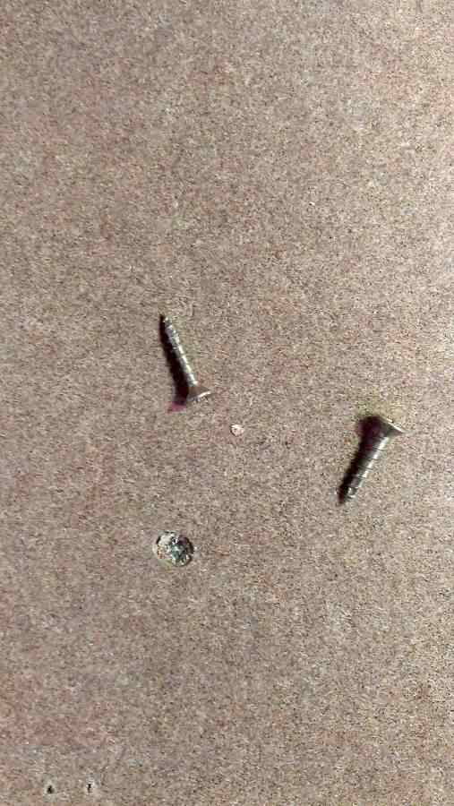
You will use screws to hold the pad while milling it
has to be in certain places where the
machine will not move through while milling your
design because THE MACHINE CAN NOT
DRILL THROUGH METAL BODIES, and in
case the pin met a metal body while moving BOOM
the machine will crash so MAKE SURE
YOUR BOARD IS CLEAN AND CLEAR OF ALL METAL
BODIES second thing the machine will drill
the inside out then the out side in respectively.
during the job you can accelerate the drilling
speed from the board on the side of the machine
you can also click on the RED button to stop the
job at anytime
ERROR
The
machine wasn't cutting through although we did the Z
direction more than the material
thickness still it didn't cut through. i had to
stop the design and re-measure my board more
than once from different sides and edges and
found out that the board wasn't flat i took average
of the heights and changed the slots thickness in the
design so as the depth of the drilling.
AS LONG AS YOU HAVE A SACRIFICE MATERIAL SHEET
below your material it's okay to go 3
to 4 mm more than your material's depth so as to get a
clean cut and avoid not cutting through jobs
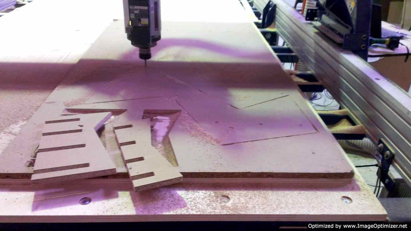
After that the job went just fine, TIP don't remove the parts while the
machine is working it's better to wait till the end
of the
job it helps balancing
the material while working
After
finishing un-drill the fixing screws then remove your
board clean all the mess, the start cleaning your
parts edges before
the assembly
>Proposal
>Digital model
>Laser Cutting
>Electronic
production
>3D Scanning
& Printing
>Electronic Design
>Molding & Casting
>Embedded programing
>Computer
controlled
machining
>Input devices
>Composites