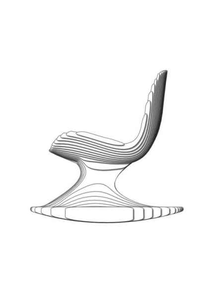
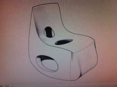
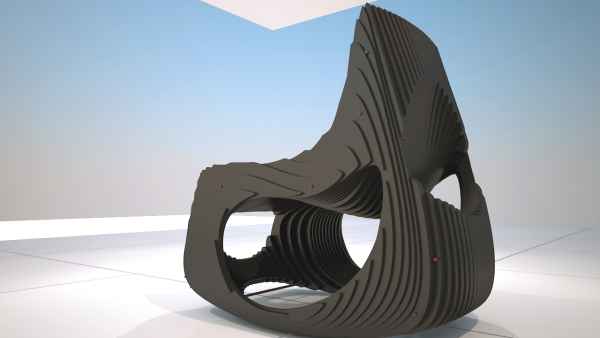
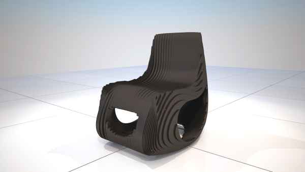
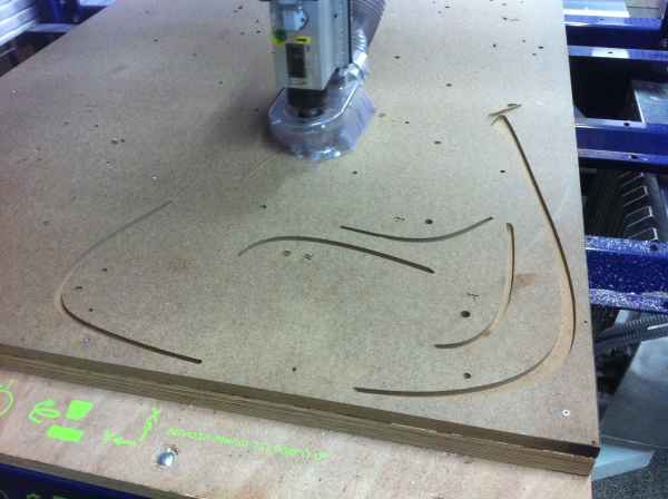
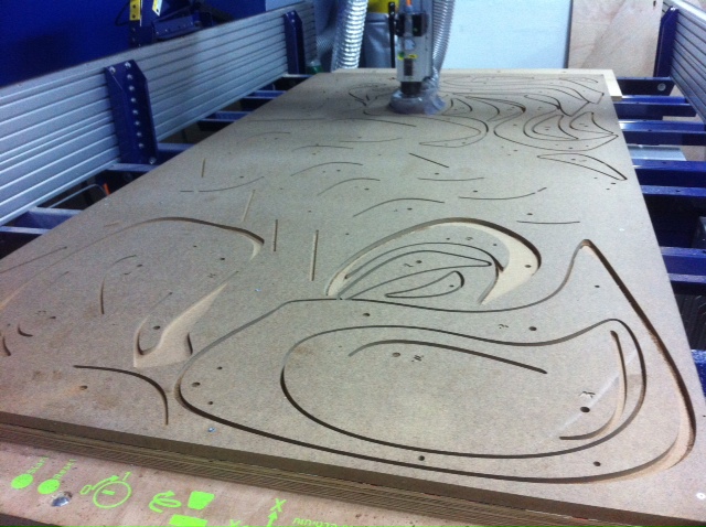
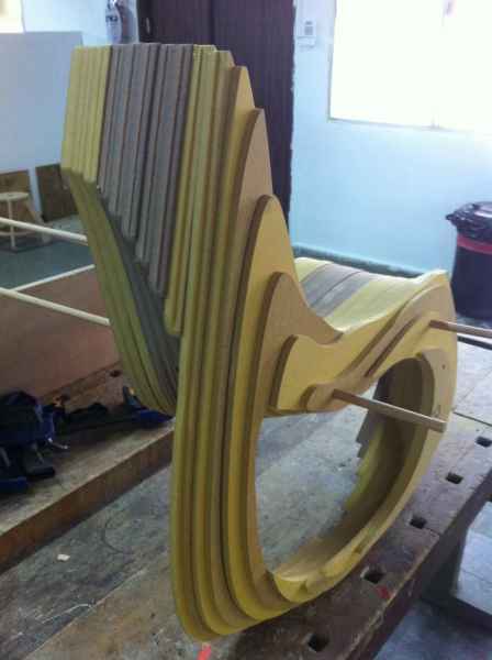
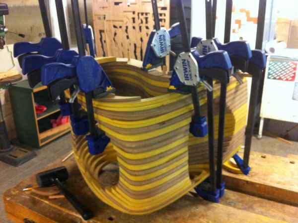
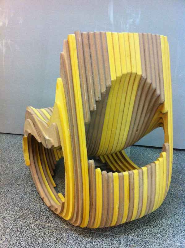
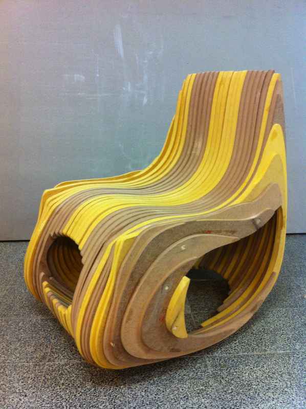
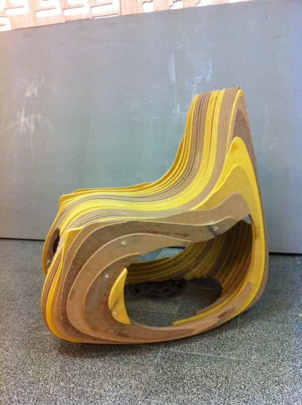
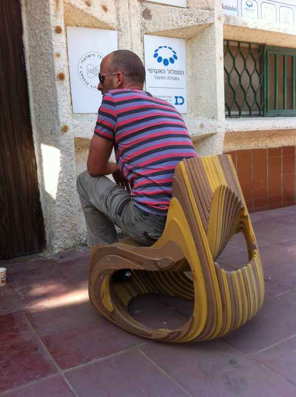
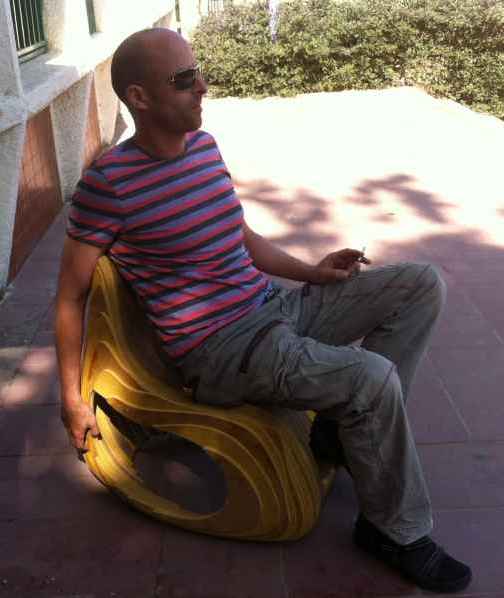
This weeks assignment was to make something big. in big scale. i decided to mile a rocking chair using the shopbot.
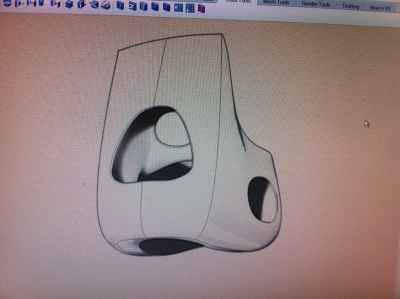
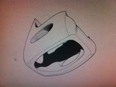
I started modeling with rhino.
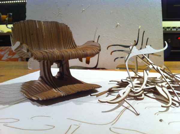
And made some models using the cardboard cut in the lazer machine.
Then i got back to rhino and made some changes in the design. i wanted to make it stronger.
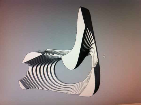
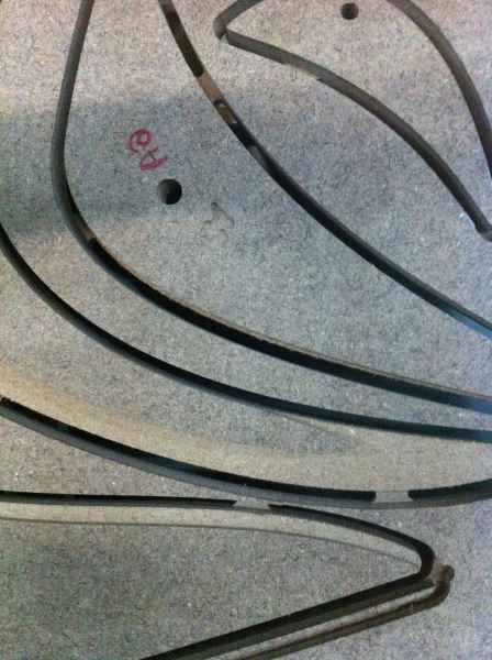
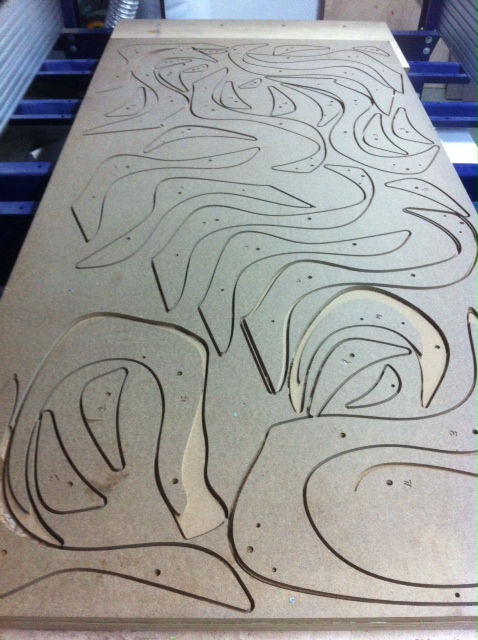
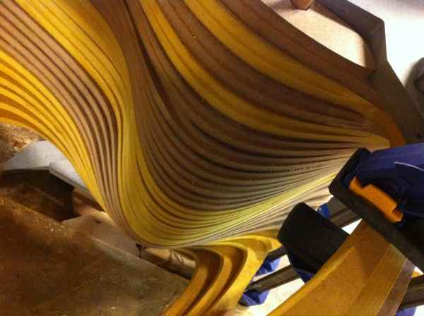
I cut the model in rhino using the contour command.I set the distance between each contour line as the thickness of the material that i am using. in this case i am usine a colored M.D.F. board, 19 millimeter width. after getting the contours, i extruded them to have a 3d model of the chair.
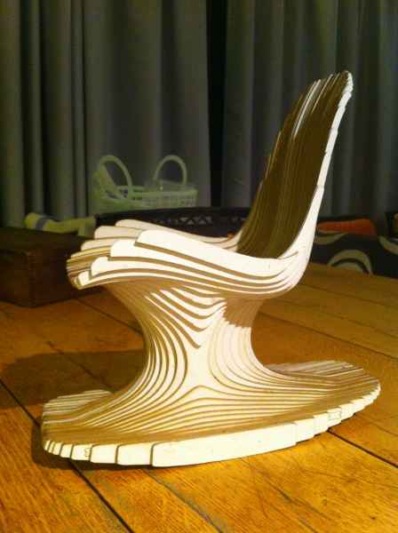
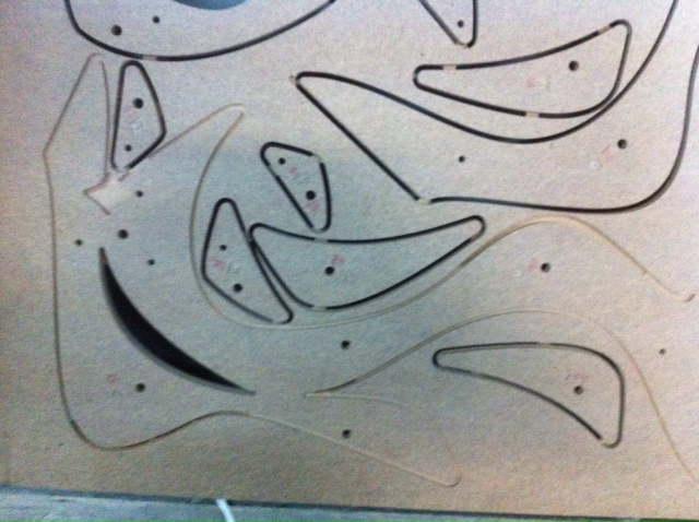
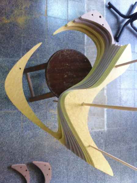
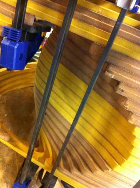
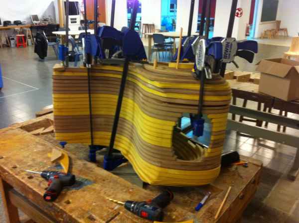
In the 3d model i added hole in the size of some round wood poles that go in 5 places throw the chair to help me in the assembling.I also numbered the pieces for the same reason.
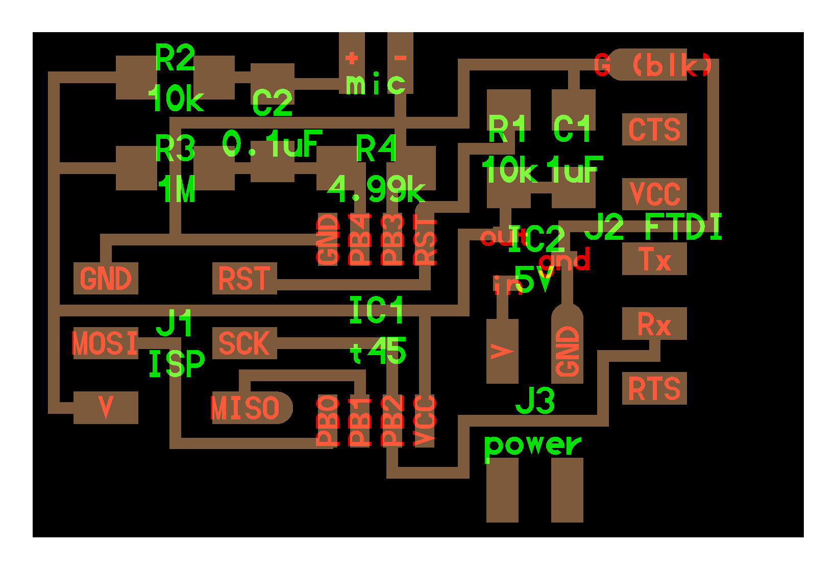
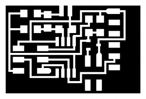
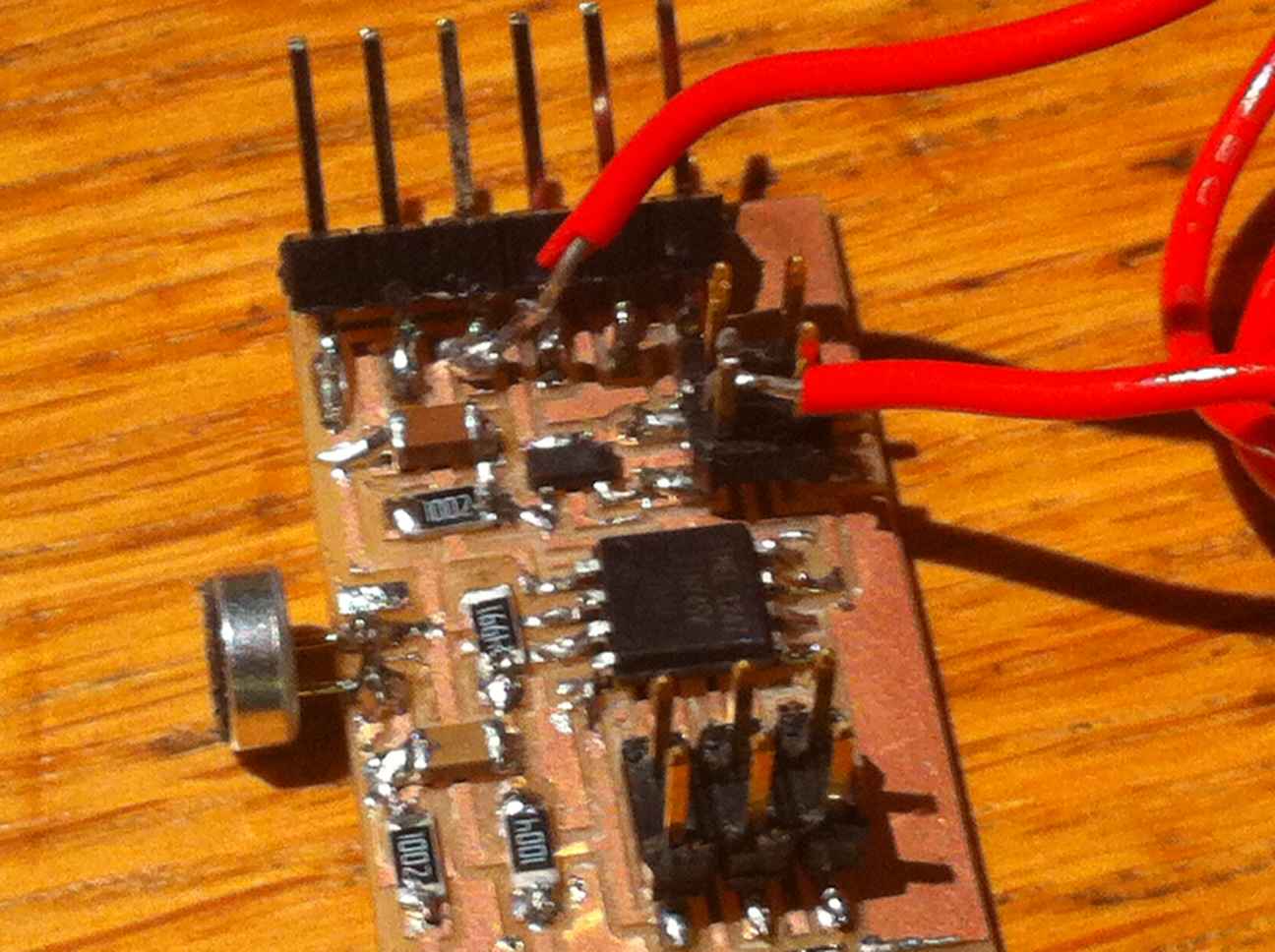
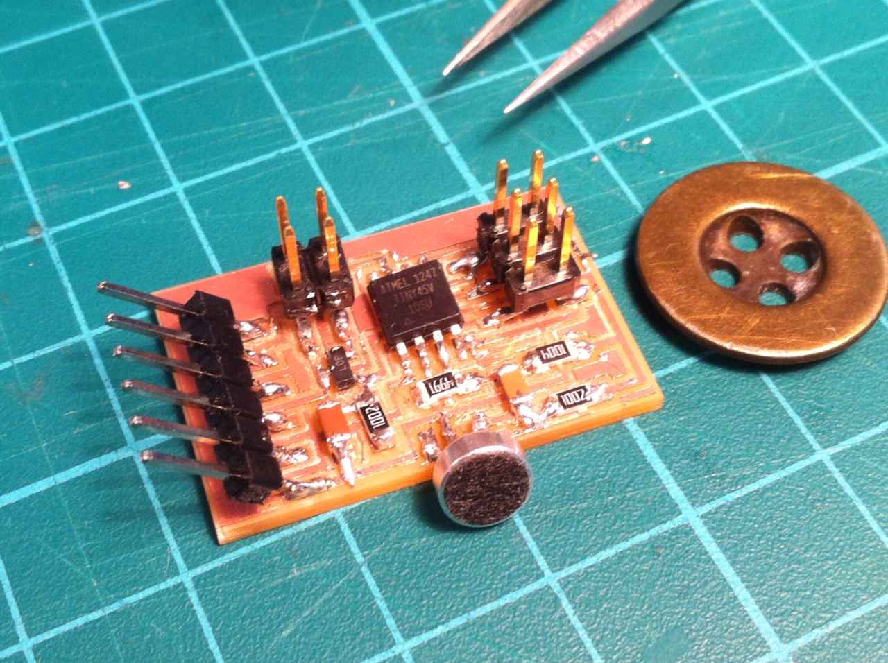
I made the hello mic 45 board, designed by neil Gershenfeld.I used the .png file to mill the board.
After soldering the parts i understood that i am not going to use an external power source (like 9v battery), so i hade to solder another wire to close the circuit.
First i programmed the board on mac. I used AVRISPmkii proggramer to upload the hello.mic.45.make file.
in the terminal type- cd Desktop .this will direct the terminal to the desk top.
then type- sudo make -f hello.mic.45.make program-avrisp2. this will use the .make file to generate a hex code from the .c file and program the board.
then type-ls /dev/tty.usb*. this will give you the name of the serial port in use. ( /dev/tty.usbserial-FTG6MXIT)
python is already installed on this computer. if not, you have to download python 2.7.3 and install it and then do the sane with python serial
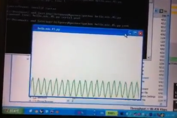
type- python hello.mic.45.py /dev/tty.usbserial-FTG6MXIT. this will upload the python code using the output from the mic to generate a graphic display.
Then i tried to do the same in windows xp. i installed python 2.7.3.
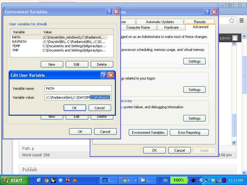
then i added python to my path:
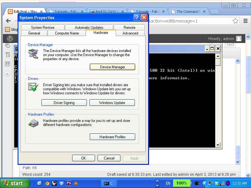
- right click on my computer and choose properties and then choose environment variables.
- edit the path and add ;c\python27.
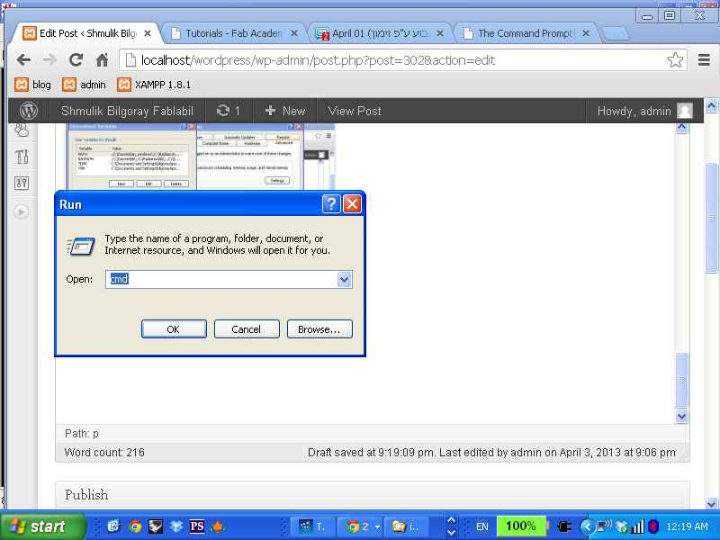
-restart the computer and open the command line.
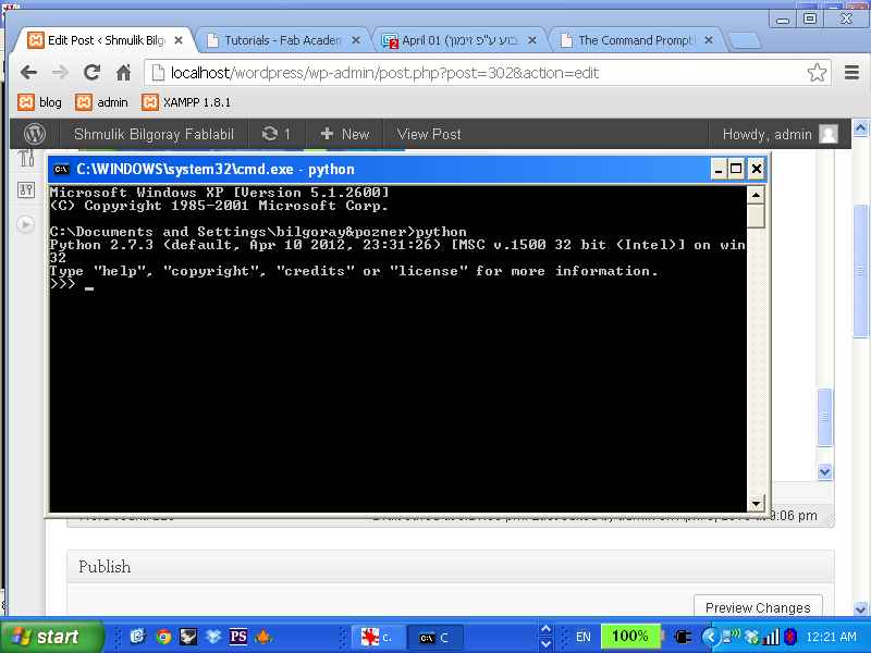
-then type in the command line python
if everything went well you should get this.
- then download and install PySerial and TKinter
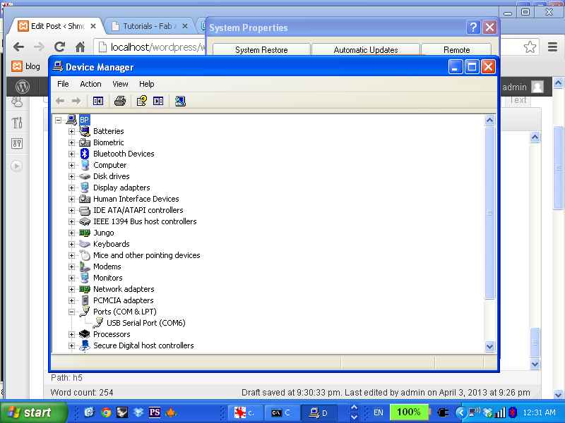
- connect the FDTI cabel and check the port number. right click on my computer,select properties ‘ select devices manager and see the number of the serial port- com6
- By Anna’s tutorial i typed in the command line python hello.mic.45.py com6 ( i moved the .py file to the directory that the command line go)
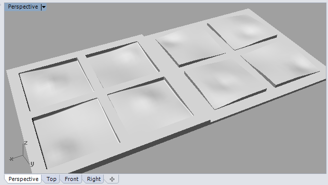
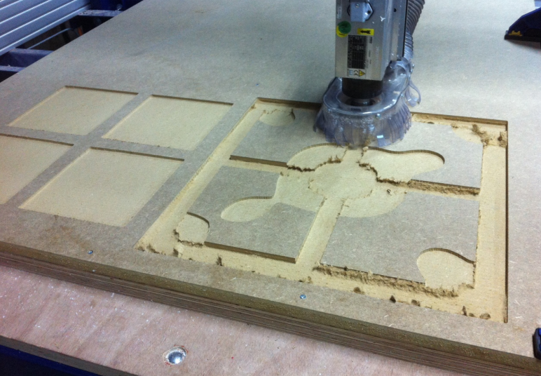
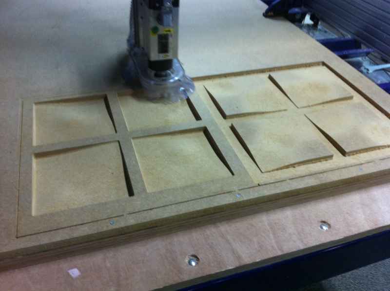
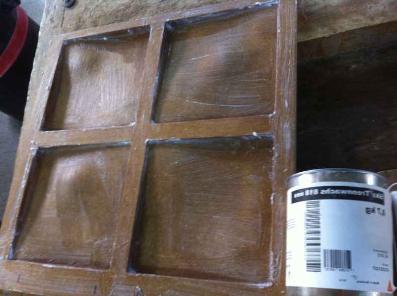
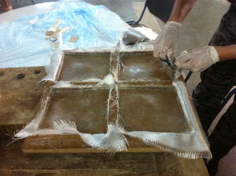
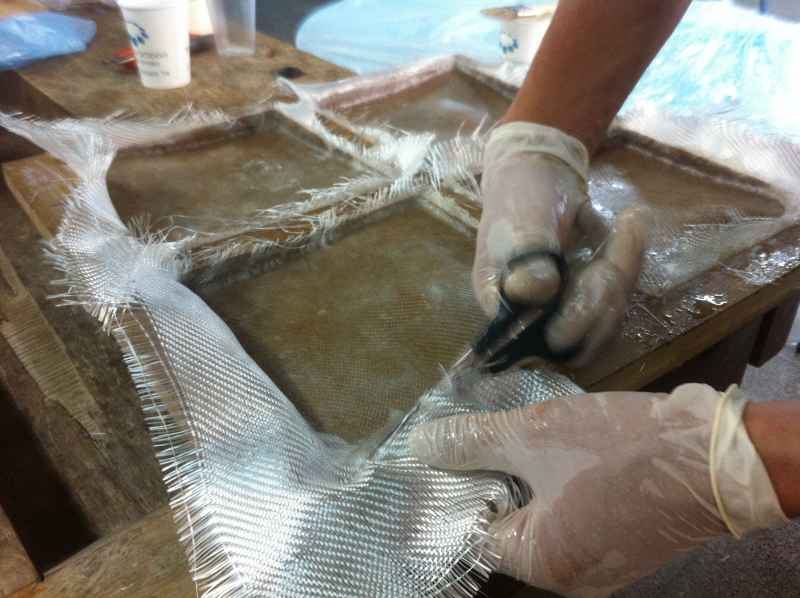
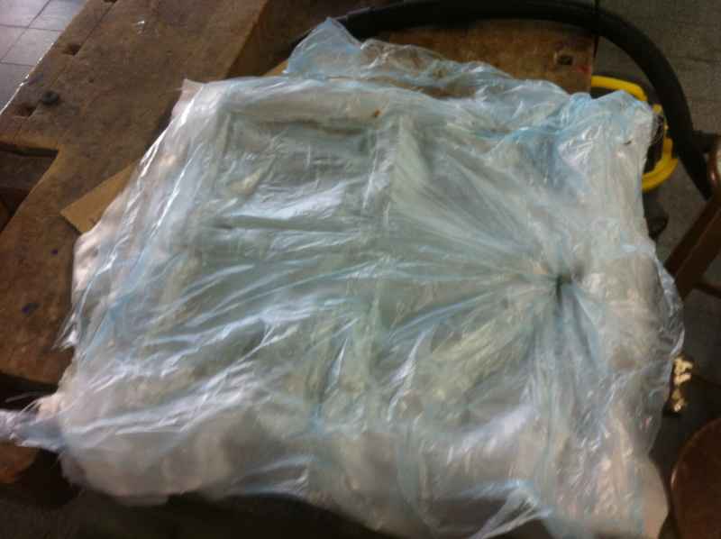
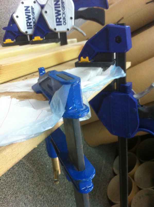
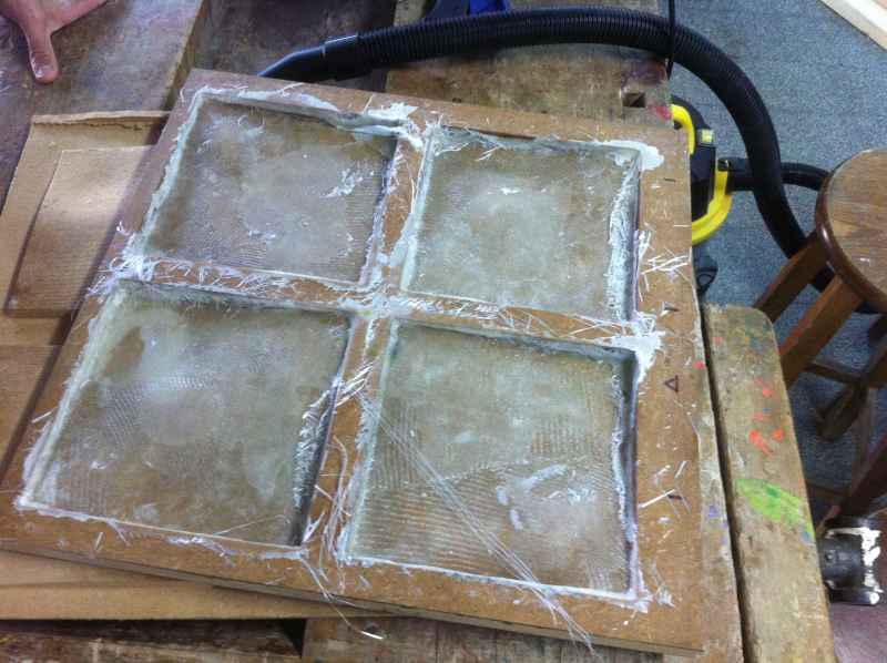
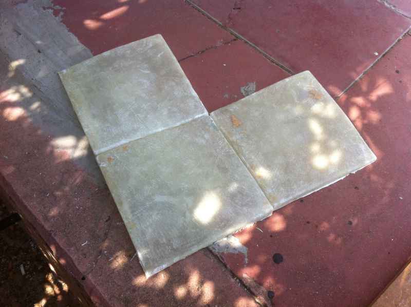
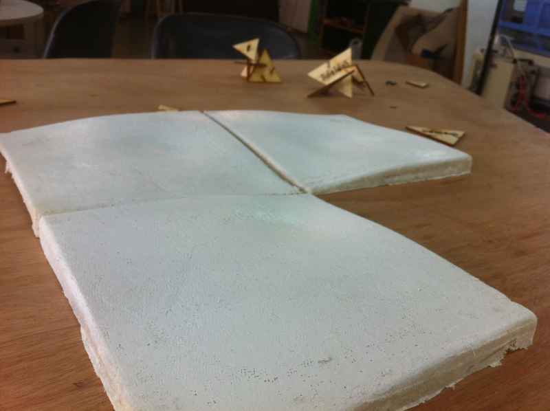
this weeks assignment is to use composite materials. I want to use fiber glass and epoxy resin to make wall tiles.
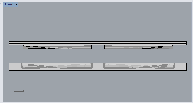
i want to mile a mold from MDF with the shopbot. I designed a mold in rhino. It is for four tiles and made of two parts so i can press the fiberglass with the resin.
it is important to make the part that press smaller so their will be enough space for the fiberglass. i offset it in 3 millimeters.
In the tutorial there is a very clear explanation on how to use the arduino that communicate with the arduino board.After i plug in the arduino board i uploaded the scatch called firefly_firmata and the bord is ready to talk to the grasshopper.
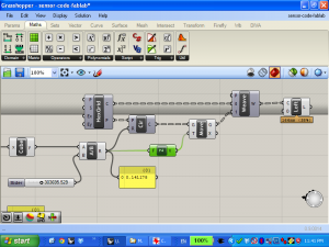
In the grasshopper interface i used the firefly toolbar to open the arduino port and read data from it.
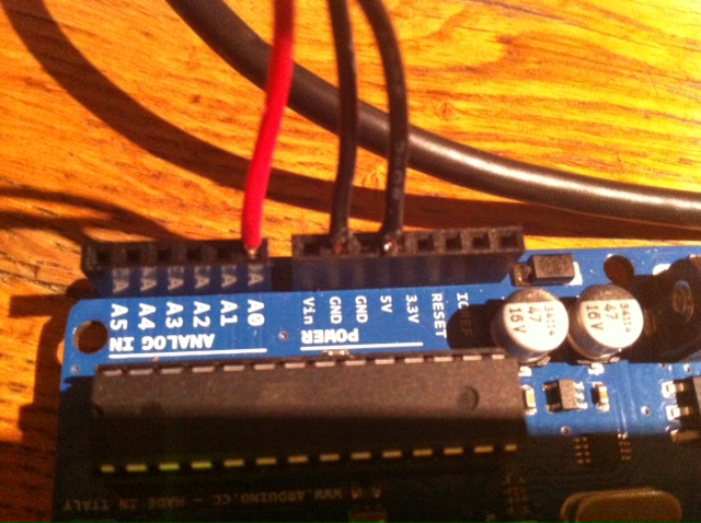
I connected a microphone sensor to the analog pin ( pin A0) and read the input from it.
then i build a simple code for some surfaces made of loft between a hex grid and a circle, getting the radius and the hight of the surfaces change by the reading from the sensor.
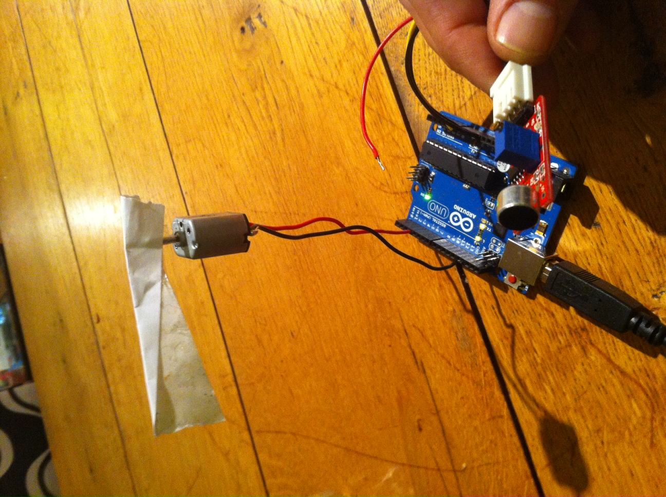
this weeks assignment was to add an output device to a micro-controller board and program it to do something. I am using the arduino uno board with firefly.
I want to control the speed of the dc motor with a microphone.I connected the mic. to analog pin A0 and the DC motor to digital pin no. 3.
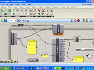
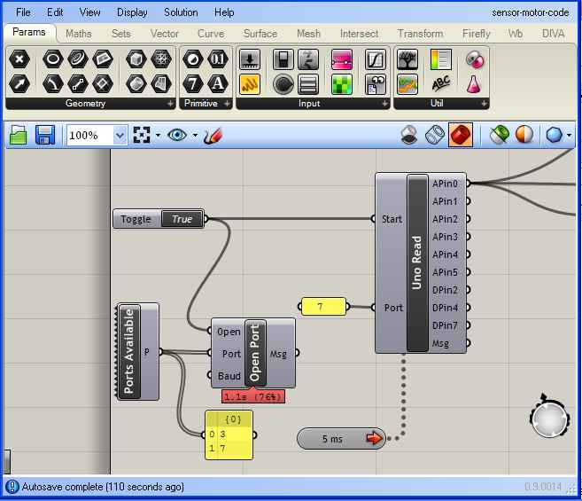
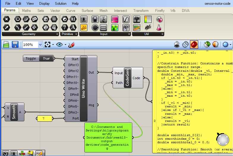
In Firefly i opened the right port ( no. 7) and added an uno read component.
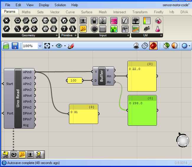
now i read data from the mic sensor attached to the arduino board.
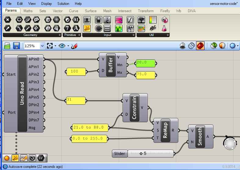
I connected a “buffer” component so i can get the minimum and maximum values of the reading.I take these values from the last 100 readings.
I approximately constrained the values that i get from the mic with the help from the data i got from the “buffer” component. The DC motor gets values from 0-255 (pwn) so i added a “remap” component to set the values from 21-88 to a 0-255 values.To make the speed change smoother i added the “smooth” component and set it’s value to 5.
Now i add a “uno write” component and plag the data coming from the “smooth” component to the digital pin no. 3 (dpin3). After i add a boolean toggle and set it to “true” at the “start” pin the motor starts to react to the mic sensor.
To the out pin of the “uno write” component i added a “code generator” component so the code can be generated to a specific location that i set in the path pin.
I closed Rhino and uploaded the file that was generated by Firefly in Arduino to the board and it warked just fine!!! here is the code from arduino:
/*
Firefly Code Generator by Andy Payne
Copyright 2011 All Rights Reserved
Code Generated on 04/24/2013 23:57:10
Special thanks to Panagiotis Michalatos.
For more information visit: www.fireflyexperiments.com
*/
#include “FFCasts.h”
//******************* Begin Function Definitions *******************
//Remap Number Function: Remap a value into a new numeric domain.
double Remap_Numbers(double x, Interval _in, Interval _out) {
return (x – _in.t0) * (_out.t1 – _out.t0) / (_in.t1 – _in.t0) + _out.t0;
}
//Constrain Function: Constrains a number to a specific numeric range.
double Constrain(double _v1, Interval _in){
double _min, _max, result;
if (_in.t0 < _in.t1){
_min = _in.t0;
_max = _in.t1;
}else{
_min = _in.t1;
_max = _in.t0;
}
if (_v1 < _min){
result = _min;
}else if (_v1 > _max){
result = _max;
}else{
result = _v1;
}return result;
}
double smoothlist_0[2];
int smoothindex_0 = 0;
double smoothtotal_0 = 0.0;
//Smoothing Function: Smooth (or average) an incoming value based on (N) number of samples.
double Smoothing_Moving_Average(double _v1, int _n, double *_list, int *_index, double *_total){
*_total -= _list[*_index];
*_total += _v1;
_list[*_index] = _v1;
(*_index)++;
if (*_index >= _n) *_index = 0;
return *_total/(double)_n;
}
//******************** End Function Definitions ********************
This weeks assignment was to build a wired &/or wireless network with at least two nodes.
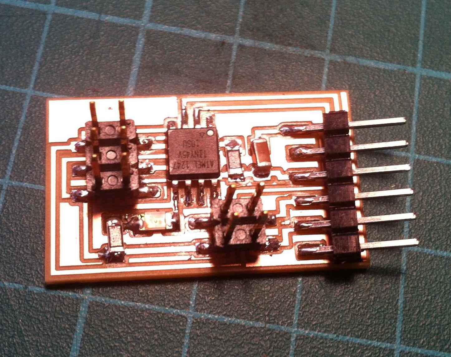
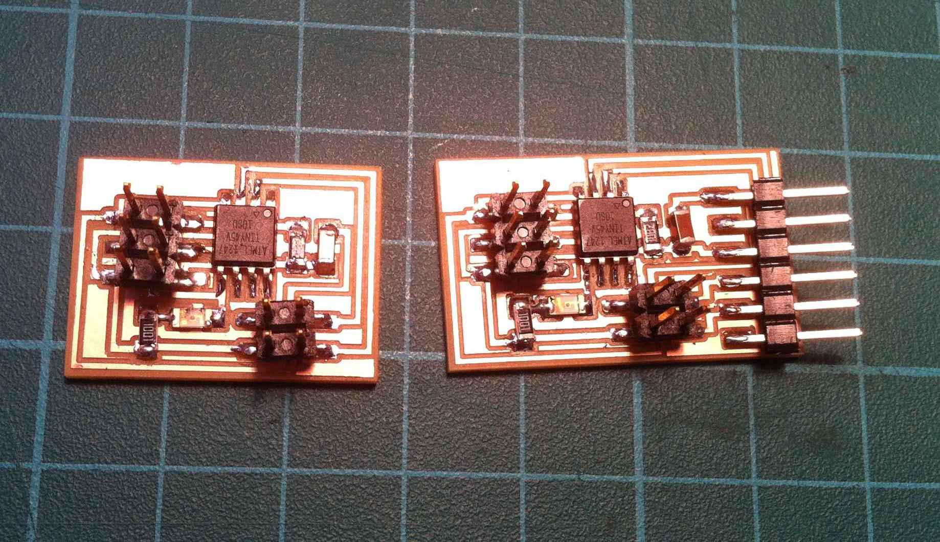
I built the hello.bus.45 network. I milled and soldered the boards.The bridge has a ftdi connector.
I downloaded the .make’, c and hex files from the Providence tutorials.
For the programming i tried to use a PC with window os but the make file could not find the avr mkII , so i finally use a MAC os.
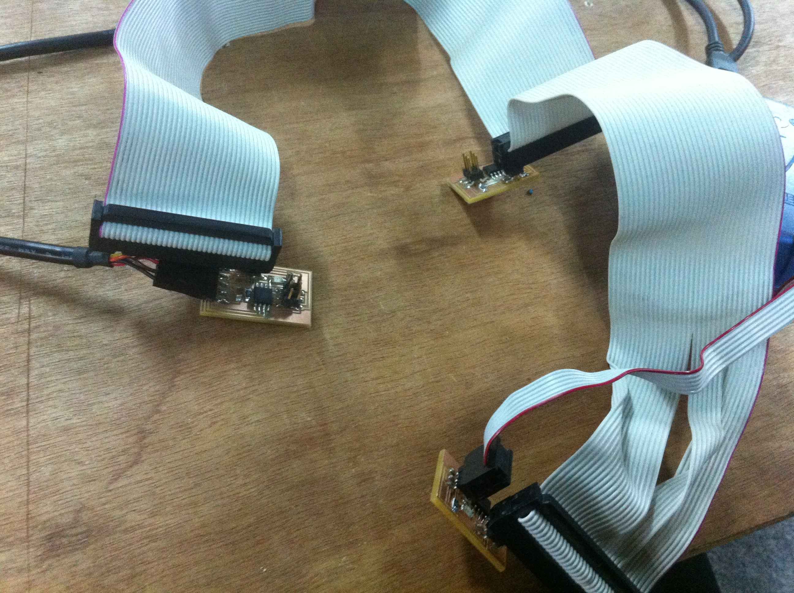
I opened the c file and changed the node id to 0 and saved the file. I connected the avr mkII to the bridge board and connected the board also to the MAC with a ftdi cabel to get the power . i got agreen flash from the avr. then i uploaded the make file to the board. in the terminal i typed - sudo make -f hello.bus.45.make program-avrisp2. now the bridge board is programmed.I disconnected the avr and used the bridge board to program the other two node boards. Before each time i programmed the node boards i open the c file and changed the node id to 1 and 2 so the node will get their id . finally i connected the three boards together.
In arduino i opened the serial monitor and typed the letter 0. The three boards flashed and the bridge ( id 0) flashed once more. i also got a feedback from the board ” node 0 “. I tested node 1 and 2 and they responded the same.