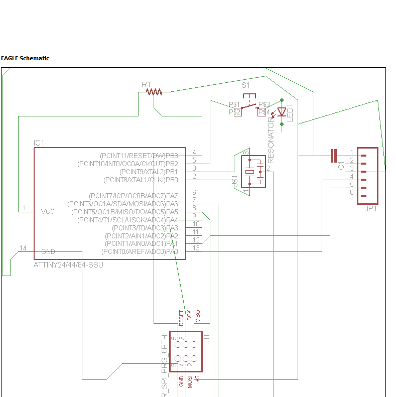
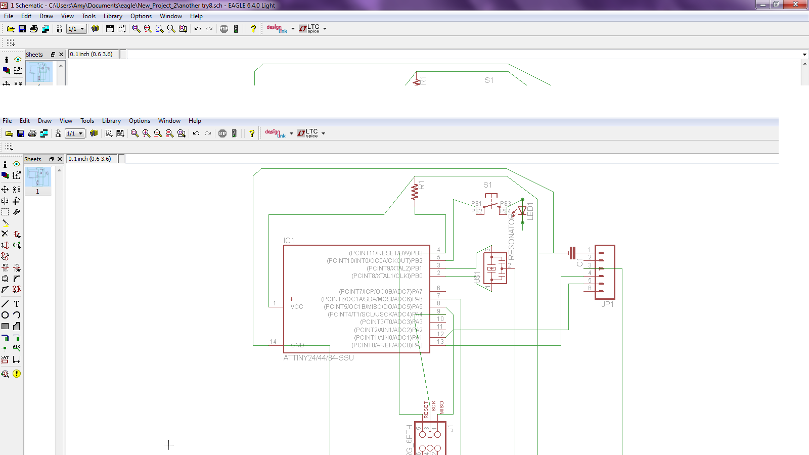
Electronics design... The week that I'm 'hating' the most so far. While I had a lot of fun during the 3D scanning, I've been cursing in every language that I know for the last week. We had to redraw this board for this weeks assignment. It sounds easy, until you start working on it.
It all started on wednesday: the moment we got the new assignment. Thoug I was still full of good motivation to start the assignment. I've never worked with electronics so I was quite curious. But... maybe instead of learning for my january exams in Belgium, I should have used the time to ask for lessons in electronics... in Dutch.
Why? Because now I'm sitting here whith stuff in front of me and I totaly have no idea what to do with it or what it does. Luckely, Frosti came to the rescue on friday. He gave me 'Electronics for dummies'. And according to the cover, it has been well used in Fablab Vestmannaeyjar. The book got me a little bit further. But not much. For example, it doesn't explain Eagle...
After trying another afternoon in Eagle, I asked Frosti for some help. It helped, but Eagle still stayed a mistery for me. It's not until the monday morning that I could finaly do something in Eagle, thanks to Bjartur. It didn't last long though. Soon I got stuck with drawing the wires in the schema and especially with the board.
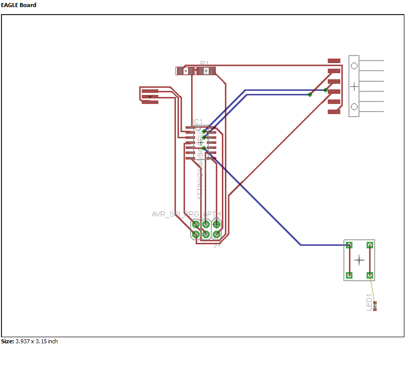
I could explain all my tryouts (goes from 1 to 7 - yes, I restarted 7 times all over again...), but I'm not going to do that because in the first tryouts the biggest mistake was to use the wrong Attiny t44. Another thing that I figured out when I put try out 4 to 6 in board form was that sometimes the lines weren't connected, thoug they looked like it in the scheme. What happend was that I didn't connect them to the END of the resonaror, crystal, ISP... After I figured that out, it went better.
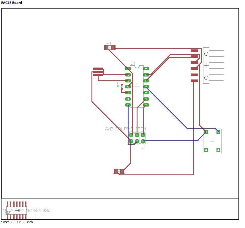
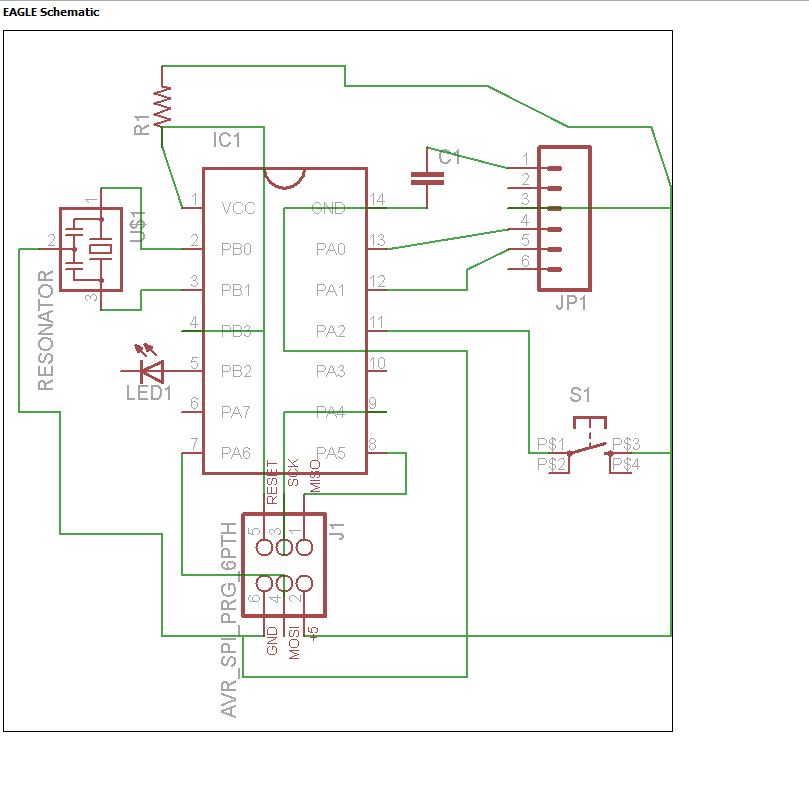
But... That's pitty enough not all. In try out 7 (with the new Attiny t44), some lines still disapear or are just connected somewhere else on the Attiny or FTDI. I keep adjusting and searching in the scheme, but can't really find anything... Any hints are welcome.
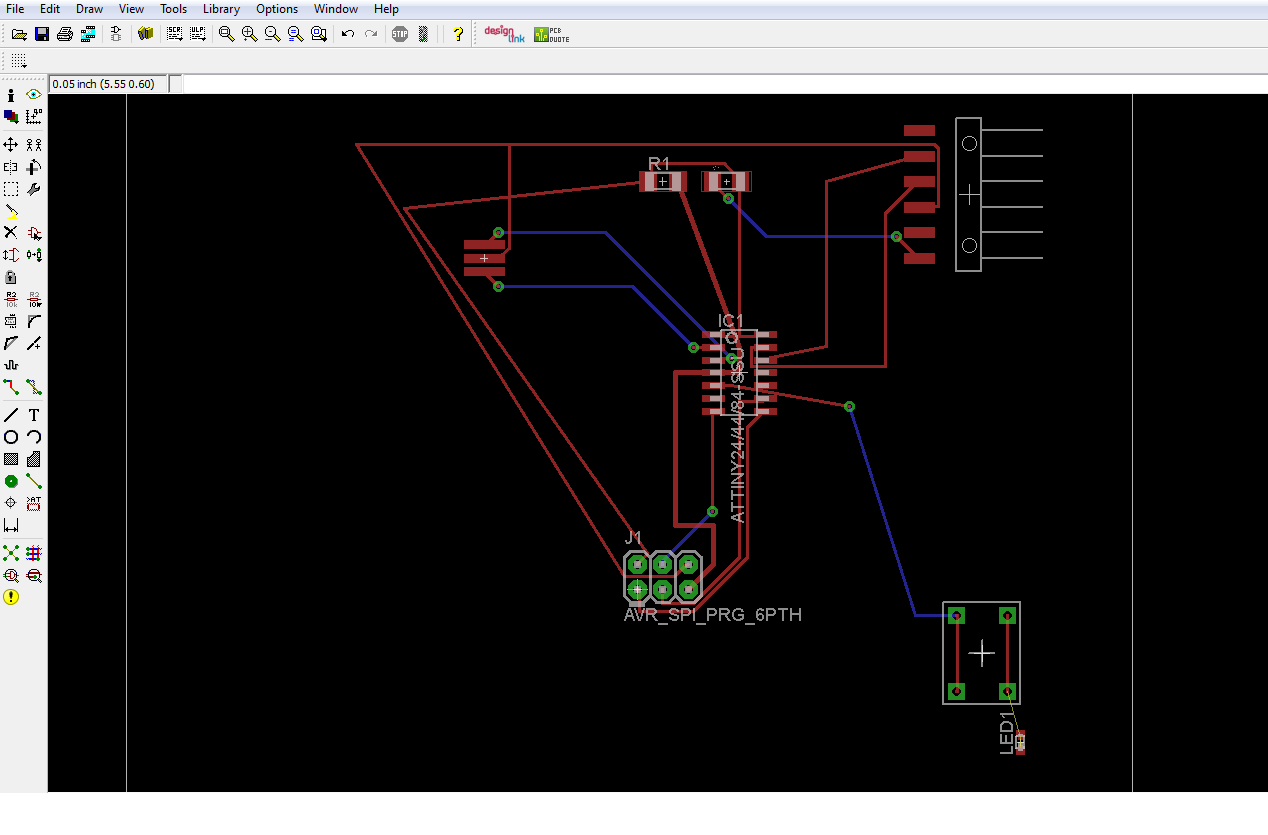
And than the last problem. I started to figure out how to work with the wrong Attiny t44. I started to see how I could put the wires, where I could put my button or LED light. But then... like said above, we used another Attiny. And now I have to start all over again with finding my way. The main problem now is that I have to many cross overs. On the board it appears as red and blue lines. The Eagle manual says that the blue lines are bottom layers. And that the red ones are toplayers. Because I don't want to add tenthousands of 0 ohm resistors, I want to get rid of the blue ones. If I've got it right in meaning and everything I just said is correct.
On tuesday evening I finaly officially gave up and sended a mail to Frosti for extra help. And as usual, the moment you give up or ask for help, some things turn out ok. Still not perfect enough to mill the board out.
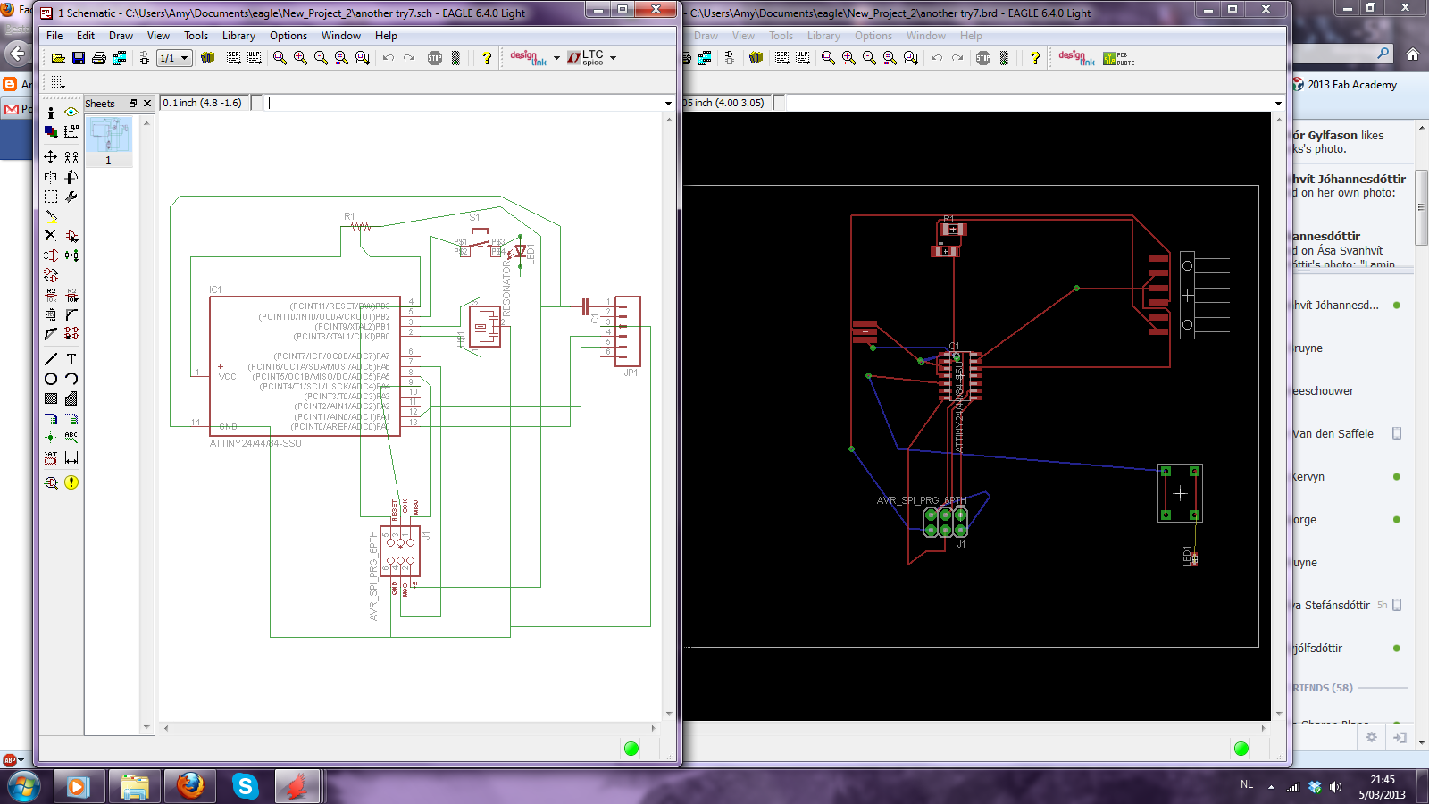
So far where I've got with the assignment of this week. Let's say that I'm disapointed in myself but hearing "Eagle" as in the program, the bird, The Eagles, metro/subway stations (the groundplan looks like a board) makes me run away with shivers. Not really the purpose of this weeks assignment. But I won't give up and I'll mannage to make it work the motivation is still there. I think that I just need a little push in the back to make this work.
On the Wiki page from Fablab Vestmannaeyjar there was a list of all the components that you should use during the assignment or where to find them. On my page here, I'll put an updated version.
- R1 10K: 01_ng.lbr -> resistor -> resistor1206
- C1 uF: 01_Sparkfun.lbr -> CAP -> CAP1206
- Xtal 20 MHz: 01_fab.lbr -> resonator
- IC1 t44: Attiny 44a chip -> SOIC14 (the last one)
- J1 ISP: 01_Sparkfun_lbr -> AVR_SPI_PRG_6 -> AVR_SPI_PRG_6PTH 2x3
- J2 FTDI: 01_Sparkfun_lbr -> M06 -> M06SMD (1x06-SMD)
- LED: 01_adafruit -> LED -> LED (smartled-TTW)
- Button: 01_Sparkfun.lbr -> button -> buttonpad-2x2SINGLE (5mm Button Pad)
