Project Sessions
WEEK 13 (17 April 2013)
[Output Devices]
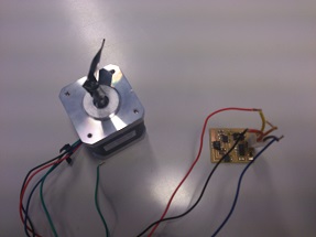
This week’s assignment was to add an output device to a microcontroller and program it to do something. In this case I chose a board to make a circuit, to use in my final project through a stepper motor (bipolar). and also at a later stage I will need a sensor led light to be connected to my pillar.
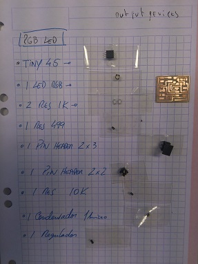
STEP 1: MANUFACTURING THE BOARDS
Hello RGB Led , will be used for my final project
The Hello stepper 44 board, will also be used for my final project
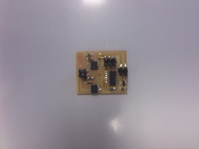
STEP 2: PROGRAMMING THE BOARD (HELLO STEPPER 44 BOARD)
The programming was made in UBUNTU following the similar procedure for the assignment INPUT DEVICE.
HELLO STEPPER 44 BOARD
hello.stepper.bipolar.44. full. C file
// hello.stepper.bipolar.44.full.c
//
// bipolar full stepping hello-world
//
// Neil Gershenfeld
// 11/21/12
//
// (c) Massachusetts Institute of Technology 2012
// Permission granted for experimental and personal use;
// license for commercial sale available from MIT.
//#include <avr/io.h>
#include <util/delay.h>#define output(directions,pin) (directions |= pin) // set port direction for output
#define set(port,pin) (port |= pin) // set port pin
#define clear(port,pin) (port &= (~pin)) // clear port pin
#define pin_test(pins,pin) (pins & pin) // test for port pin
#define bit_test(byte,bit) (byte & (1 << bit)) // test for bit set#define bridge_port PORTA // H-bridge port
#define bridge_direction DDRA // H-bridge direction
#define A2 (1 << PA0) // H-bridge output pins
#define A1 (1 << PA1) // "
#define B2 (1 << PA3) // "
#define B1 (1 << PA4) // "
#define on_delay() _delay_us(25) // PWM on time
#define off_delay() _delay_us(5) // PWM off time
#define PWM_count 100 // number of PWM cycles
#define step_count 20 // number of stepsstatic uint8_t count;
//
// A+ B+ PWM pulse
//
void pulse_ApBp() {
clear(bridge_port, A2);
clear(bridge_port, B2);
set(bridge_port, A1);
set(bridge_port, B1);
for (count = 0; count < PWM_count; ++count) {
set(bridge_port, A1);
set(bridge_port, B1);
on_delay();
clear(bridge_port, A1);
clear(bridge_port, B1);
off_delay();
}
}
//
// A+ B- PWM pulse
//
void pulse_ApBm() {
clear(bridge_port, A2);
clear(bridge_port, B1);
set(bridge_port, A1);
set(bridge_port, B2);
for (count = 0; count < PWM_count; ++count) {
set(bridge_port, A1);
set(bridge_port, B2);
on_delay();
clear(bridge_port, A1);
clear(bridge_port, B2);
off_delay();
}
}
//
// A- B+ PWM pulse
//
void pulse_AmBp() {
clear(bridge_port, A1);
clear(bridge_port, B2);
set(bridge_port, A2);
set(bridge_port, B1);
for (count = 0; count < PWM_count; ++count) {
set(bridge_port, A2);
set(bridge_port, B1);
on_delay();
clear(bridge_port, A2);
clear(bridge_port, B1);
off_delay();
}
}
//
// A- B- PWM pulse
//
void pulse_AmBm() {
clear(bridge_port, A1);
clear(bridge_port, B1);
set(bridge_port, A2);
set(bridge_port, B2);
for (count = 0; count < PWM_count; ++count) {
set(bridge_port, A2);
set(bridge_port, B2);
on_delay();
clear(bridge_port, A2);
clear(bridge_port, B2);
off_delay();
}
}
//
// clockwise step
//
void step_cw() {
pulse_ApBp();
pulse_AmBp();
pulse_AmBm();
pulse_ApBm();
}
//
// counter-clockwise step
//
void step_ccw() {
pulse_ApBm();
pulse_AmBm();
pulse_AmBp();
pulse_ApBp();
}int main(void) {
//
// main
//
static uint8_t i,j;
//
// set clock divider to /1
//
CLKPR = (1 << CLKPCE);
CLKPR = (0 << CLKPS3) | (0 << CLKPS2) | (0 << CLKPS1) | (0 << CLKPS0);
//
// initialize bridge pins
//
clear(bridge_port, A1);
output(bridge_direction, A1);
clear(bridge_port, A2);
output(bridge_direction, A2);
clear(bridge_port, B1);
output(bridge_direction, B1);
clear(bridge_port, B2);
output(bridge_direction, B2);
//
// main loop
//
while (1) {
for (i = 0; i < step_count; ++i) {
for (j = 0; j < i; ++j)
step_cw();
for (j = 0; j < i; ++j)
step_ccw();
}
for (i = step_count; i > 0; --i) {
for (j = 0; j < i; ++j)
step_cw();
for (j = 0; j < i; ++j)
step_ccw();
}
STEP 3: ADDING OUTPUT DEVICES
Finally, I connected the stepper motor and it runs very well
Here I show the video
I tried the Neil program hello.stepper.bipolar.44 , I'll take this stepp motor for my final project, I have to study how to change the code to make the moves I need for my pillar.
I definitely believe that this task has been very helpful . While the programs we have been given hope I research and learn more about the language C parameters, to modify and customize the program according to the ouput devices I will need for my final project.

