Classes >>embedded programming
STEP 1: INSTALLNG THE PROGRAMS
For this task I choose 2 programs to work
AVR Studio 5 following the tutorial http://fab.cba.mit.edu/classes/MAS.863/people/prashant.patil/ep.html.
and Arduino following the tutorial http://academy.cba.mit.edu/2012/labs/providence/tutorials/09.html which was proposed by Anna Kaziunas France - Providence and thanks for that.
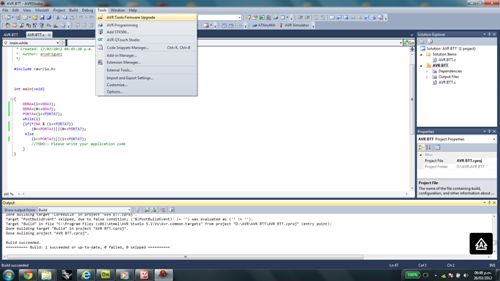
STEP 2: PROGRAMING WITH AVR Studio 5
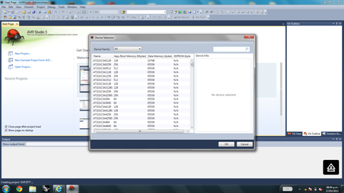 |
|
 |
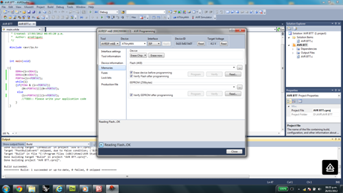
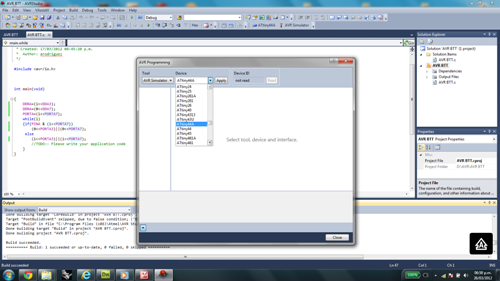
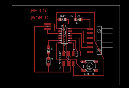
Using the C programming language, the AVR program allowed me to set my microprocessor Hello World The following figure I respected the initial port board design (A7 for the led and resistor and B2 for the switch button) which let me to run the program but unsuccessfully when connecting the AVR ISP2 with the board
|
 |
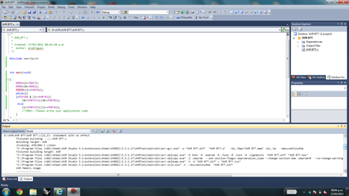
THE INITIAL PROGRAM int main(void) { |
 |
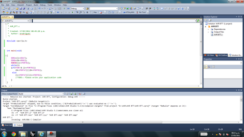
THE MODIFIED PROGRAM { |
 |
 |
STEP 3: PROGRAMNG WITH ARDUINO IDE
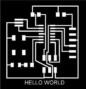
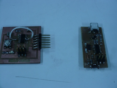
On the left you can see the old design of my echo Hello World with the switch button on the B2 port. With this design it was impossible to succeed in the programming of the microprocessor.
I had to change the design of my board as showed on the right picture. To get it on my last board I made a jumper wire to connect A3 port intead B2 port but it is clear that it is not the best way, really it is necesary to build another board
 |
 |
I tried to follow the tutorial for Arduino 1.0 and after download it we need to:
Download the ATtiny.zip and FTDI drivers
Create a folder "hardware" in the Arduino sketch folder and copy inside the ATtiny folder
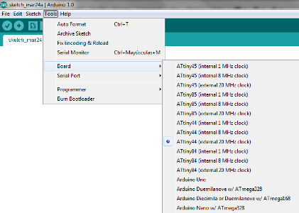
Check for ATtiny entries in the Tools menu
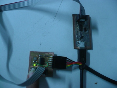
Make the connection between the fabISP programmer and the HELLO WORLD board with a ftdi wire, the miniUSB from the fabISP and the computer and finally the FTDI connector from the HELLO WORLD board and the computer
Select the "ATtiny44(external 20 Mhz clock) from the tools menu
Run "Burn Bootloader"
  |
 |
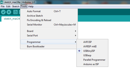
Once we had installed the Arduino we have to set: The "Attiny44 ( 20MHz )from the Menu "tool/board" The correct port from the Menu "tool/SerialPort" . Cheking device manager in "Ports Com" Select the "usbtiny from "Menu "tool/programmer" "Burn Bootloader" |
To test th program I have to use The HELLO WORLD board modified because I need to change "B2" port by "A3" port, making a jumper wire. Soon, I will have to make another board with the correct design.
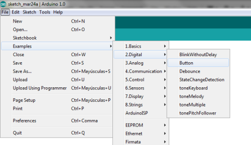
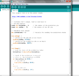
Finally, open the Button file from the examples menu and modify the ports' pins
Program the board seleccting USBtinyISP from the Tools menu
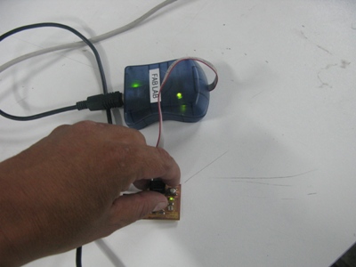
Press the button to turn on the led
  |
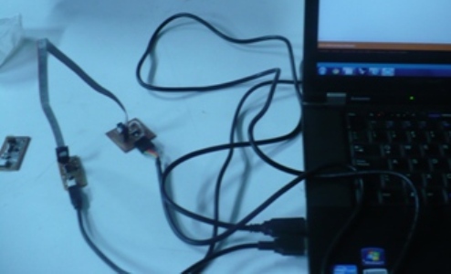
Here it is the original boad with the jump wire to change the ports. Bellow, the picture on the left show the failed intention of programming the original board |
|
 |
Like the previous task, this was a great experience and challenge where I hope to get more skills with the aim of my final project.