Model and Design
Over the past week the overall design of the low cost CNC machine has changed several times. I have come to a point that I feel the desgin is finalized and where it needs to be in order for the machine to work properly.
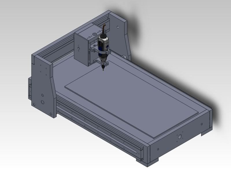
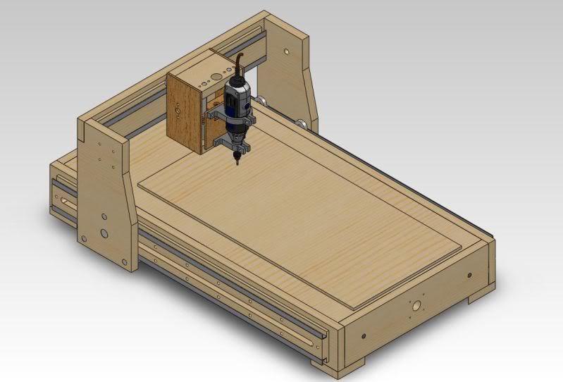
Seen below is a picture of the overall final design. The model does not feature the motor mounts, motors or drive rods yet but their size and shapes have been accounted for in the design and mouting holes are in some places on the model. The top build plate in the model and the corner blocks used as feet, will help to square the frame and keep it square durring constrution and operation of the machine.
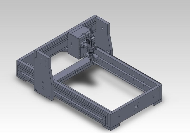
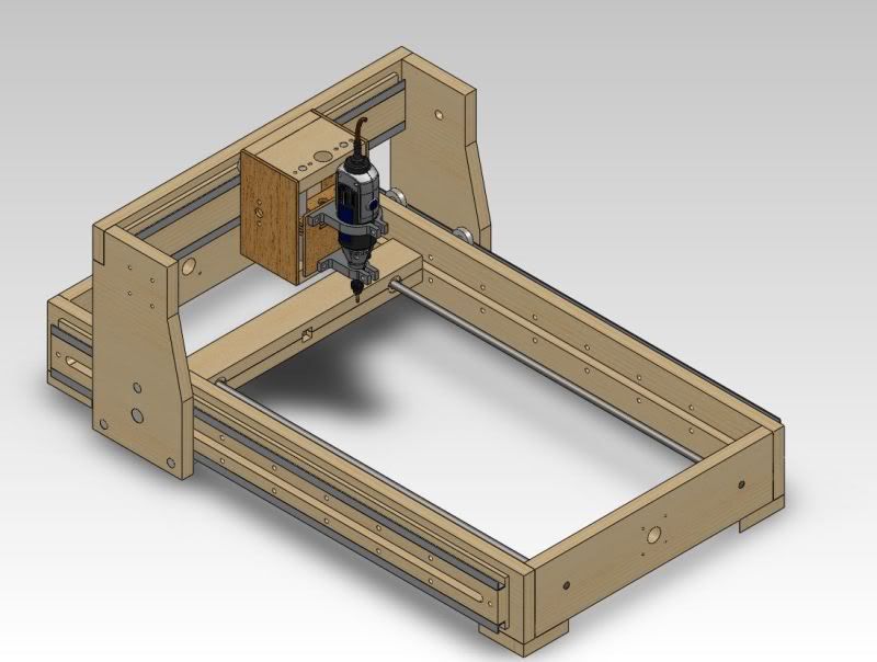
The image below shows the CNC machine without the top build plate in order to reveal the arm that pushes and pull the gantry arm. The arm is made of 2 pieces of 3/4" ply wood that have been laminated together in order to create a much stiffer arm and to allow for oilite linear bearings to be mounted into them to help keep the arm from binding to one side or another.
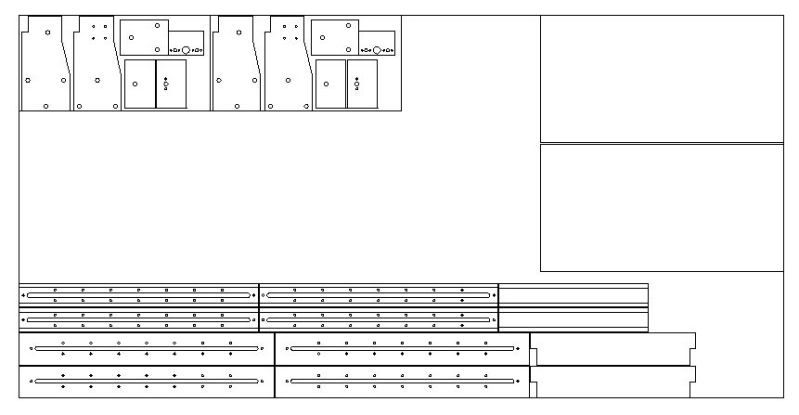
With the machine design in its final stages I was able to export all of the parts from SoildWorks into Auto CAD in order to lay them all out on a 4' x 8' sheet of playwood to maximize how I made my cuts. The picture below shows the layout of all of the parts on a 4' x 8' sheet of 3/4" plywood. The two boxes containing many of the smaller parts in the upper left hand corner would be cut out as 1' x 2' plates. The plates would then be put in the laser cutter to create scoring on the top surface of the wood to show where to drill holes and where to cut. This could all be done through measurements, however, this will give a much more accurate layout of all of the parts on the plate.
One other thing that you might notice is that there are twice as many parts as what is needed to make 1 low cost CNC machine. That is because after seeing how many parts could be made from one full sheet I decided to make a second machine to test another bearing style with. All of the same electronics would be used and the cost of the second machine with a V Groove and channel bearing style would be approximately $50 more.
Electronics
The elecronics that I plan on using are those from the MTM Snap. Due to the machine being a smaller scale version of the overall possible design I chose to use stronger stepper motors that would help to make the size transition easier. This means that some minor changes needed to be made to the MTM electronics. By replacing the 4.99k resistors with 3.7k resistors I can drive high torque 2 amp steppers that will allow me to push and pull a larger/heavier gantry system in a scaled up version.
On to the questions!
What questions need to be resloved?
What tasks need to be accomplished?
What will happen when?
An updated list of parts, costs and vendors will be available in the next update due to parts changing from the orginal build and my use of parts that I have on hand.
Special Thanks
Special thanks to Nadya Peek and Anna Kaziunas France for their help in teaching me how to understand and upgrade the MTM snap boards to handle 2amp stepper motors.