This assignment has two parts:
---Make Board Electronics
---Use Interface
Make Board Electronics
This part it's compounded for 1 bridge and 1 node


bridge-----------------------------------------
-----------------------------------node
Well, you must first download these files:
--For the bridge
Traces and
Interior
--For the node
Traces and
Interior
Work is done in the modela and proceed to solder.
The programming follows a sequence, first the bridge, then the nodes.You must download files from here:
Archivo Make
Archivo C
One observation:
For each node must be modified hello.bus.45.c in line 41 #define node_id '0'. Then assigns
--For bridge #define node_id '0'
--For node 1 #define node_id '1'
--For node 2 #define node_id '2'
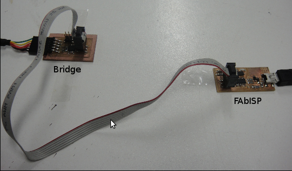
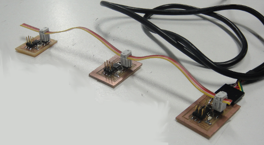
For programming each of the nodes are connected as shown in Fig.
The instrucctions for programming:
---sudo make -f hello.bus.45.make program-usbtiny
---sudo avrdude -p t45 -P usb -c usbtiny -U flash:w:hello.bus.45.c.hex
After flashing all the nodes and the bridge, and display it
Use Interface
The instructions:
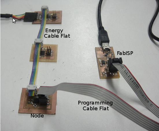
Plug your bridge into your computer (with the nodes attaches).
Connect the nodes with a cable as shown in the picture.
Open a Arduino IDE
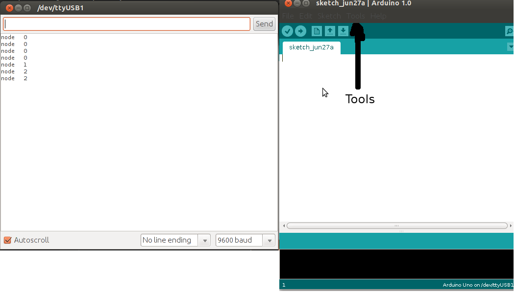
Open the serial monitor from the "Tools" menu > serial monitor
Make sure the baud rate is set to 9600.
Enter number of a note (pick a number) into serial monitor - press the
The LEDs on all the boards should light up once.
After all the boards light up, the board with the number you entered into the serial monitor should light up again.
The node name (ex: node 1) should also be displayed on the serial monitor.
See the result as follows:
Here I leave a video