This weeks assignment was to mill the board for the Fab ISP, solder on the components and program the board. To mill the board I used the Roland Modela cnc mill. I opened the file and loaded it. Put a 1/64" end mill in the spindle and ran the file to mill the traces. After sucussfully milling the traces I changed the bit to a 1/32" end mill and cut out the board. The milling process was smooth like butta and I was ready for solder. Before soldering any components to my board I put paste flux onto all of the solder pads with a Q-tip. I tinned the first pad for my IC positioned it so all the legs lined up with the pads and soldered it in place. After soldering all the legs of the IC, I moved on to the other components. I used the same process of tinning one pad and fixturing the component the soldering the other pads. I did all of the resistors, then the caps, diodes and then the crystal osilator. I soldered all of the small components then moved on to the six pin header and finished with the mini USB connector. The soldering process went pretty smoothly, the only component that gave me trouble was the mini usb. I soldered the pins first and then the mounting pads. I should have done it in reverse so the connector would have been fixtured better before I soldered the pins. After I completed the soldering it was time to program the IC. I plugged the board into the usb port and passed the "smoke test". I connected to a USBtiny programmer the make file was already edited so I didn"t have to mess with it. I typed "make clean" and got a successful response. Next I typed "make hex" and again was successful. I contiued with "sudo make fuse" and "sudo make program" again no errors. With the programming complete I disconnected the USBtiny and plugged my FabISP into the computer to see if it recognized it. It did not. I started looking around on my board to see if I could find any issues. With the naked eye everthing looked fine. I then looked at it with a magnifying lens I scavenged from a flat bed scanner. I concentrated my search to the mini USB because that was where I had the most trouble soldering. I found that my ground pin was floating above the board and not connected. To document the problem I taped my magnifier to my camera lens and was able to take a decent picture.
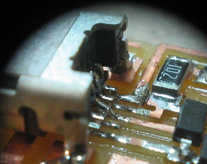
After finding the problem I resoldered the ground pin, tested the board and had success. I know have a working FabISP