This week has been a total disaster and I've not been able to get to the actual core component of the lesson due to fabrication issues with the boards.
What we did:
• Installed a bunch of drivers and installers which allow us to load the drivers onto our chips and make them run
• Modified Arduino libraries with downloaded presets made for FabISP.
• connected a bunch of different cables to the FabISP (miniUSB to computer for sending/receiving data, FTDI to Button+LED) and a bunch of cables to the Button+LED (FTDI from FabISP, miniUSB to computer for power only)
I broke mine by plugging it in the wrong orientation. The board smoked and burned out. Prior to this experience, I had no idea that there was a right or wrong orientation for these plugs. This should be mentioned in the tutorial or addressed somehow.
I built a second board. It also burned out. It's possible that the cable I used was faulty. It's also possible that there was something subtly wrong with the traces on the board.
14 mar 2012 19:53
I decided to start again completely from scratch. I went back into EAGLE and redesigned my board from the ground up. I made the traces thicker and spaced them further apart than in the previous board. The final design matches the example board more closely in its layout.
Too frightened to plug the boards in unsupervised, I opt to wait until tomorrow for the next steps.
15 Mar 2012 18:06
Arduino:
Attempted to mill out the Hello Arduino board. 1st attempt was a failure because I modified the xmin and ymin coordinates for the second tool pass (the cut out board pass), thinking I could get a closer tolerance. Wrong. It left a big margin on one side and bisected the traces on the other side.
Made a second milling attempt, this time forearmed with the knowledge that I will run both passes from the same coordinates.
Failed for a different reason. In the process of milling, some of the copper traces were pulled off of the surface by the tool bit. I suspect that this is because the bit was dull. From now on I am always going to assume that pre-used bits are dull and will take a new bit for myself every single time I start a job that uses the 1/64" bit.
Milled a third Arduino board. Seems OK but who knows.
Button+LED:
Turns out I soldered the chip onto the board in the wrong orientation. Had to desolder it. Pulled up the copper traces in the process and another board is now ruined.
The orientation of the chip can be determined by the small circle in the corner.
Back to milling.
21 March 2012,
6:30 am
I have milled and soldered my 4th Button+LED board. I have checked and double-checked and triple-checked the orientation of all components, and noted the correct way to orient all cables when plugging the device in.
7:04 am
I plug my Button+LED into my FabISP, and I plug both devices into the USB ports on my MacBook Pro.
I load up the Arduino application.
I double-check to ensure that "ATtiny44 (external 20 MHz clock)" has been selected from the Boards menu. It has.
I run "Burn Bootloader", and:
initialization failed, rec=1 Double check connections and try again, or use r-F to override this check
Well, shit.
I open up "System Information" (formerly System Profiler). I find that the FabISP and the FTDI cable are both listed under the USB heading:
FabISP:
Product ID: 0x0c9f Vendor ID: 0x1781 Version: 1.04 Speed: Up to 1.5 Mb/sec Location ID: 0xfd120000 / 4 Current Available (mA): 500 Current Required (mA): Unknown (Device has not been configured)
TTL232R-3V3:
Product ID: 0x6001 Vendor ID: 0x0403 (Future Technology Devices International Limited) Version: 6.00 Serial Number: FTF4ZGDJ Speed: Up to 12 Mb/sec Manufacturer: FTDI Location ID: 0xfa130000 / 6 Current Available (mA): 500 Current Required (mA): 90
At this point I'm stumped. I will re-check all my solder connections and try one more time, but other than that I have no idea what is wrong or why this isn't working. So that's as far as this week's assignment has gotten after four boards and many hours of milling, soldering, desoldering, rereading documents an rewatching Neil's lecture video. I haven't even made it to the Arduino portion of this project and thus far haven't had an opportunity to do any actual programming. Hopefully this can be resolved soon but to tell the truth I'm getting extremely frustrated and feel pretty lost.
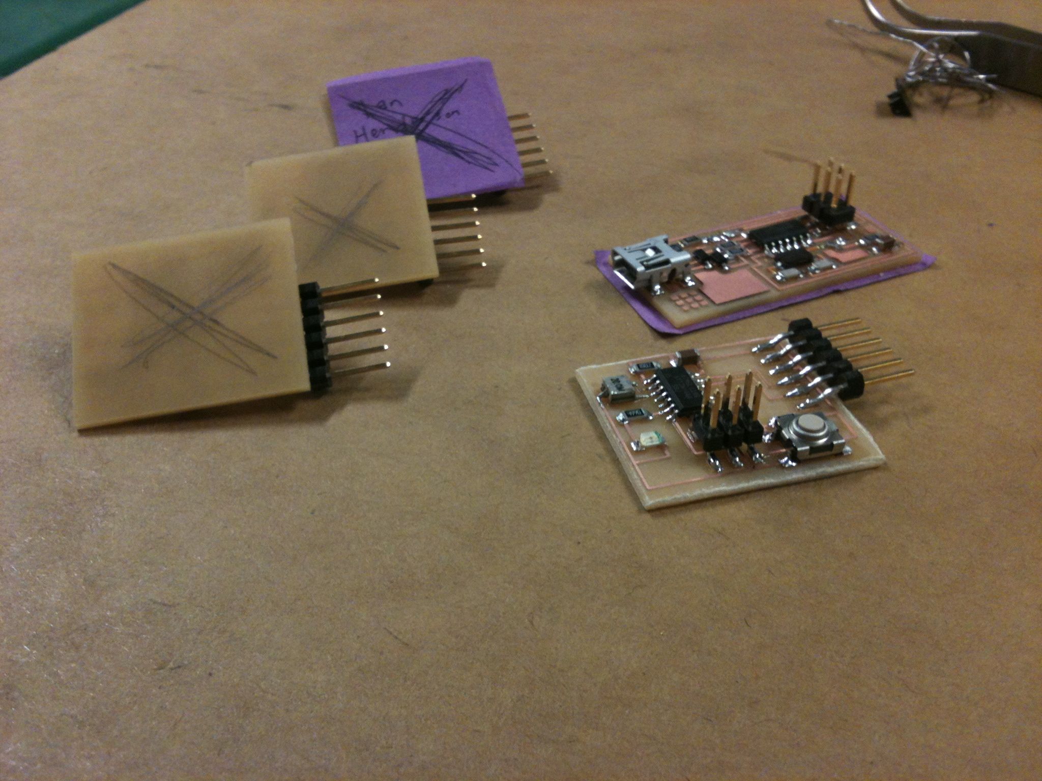
milling 4th Board:
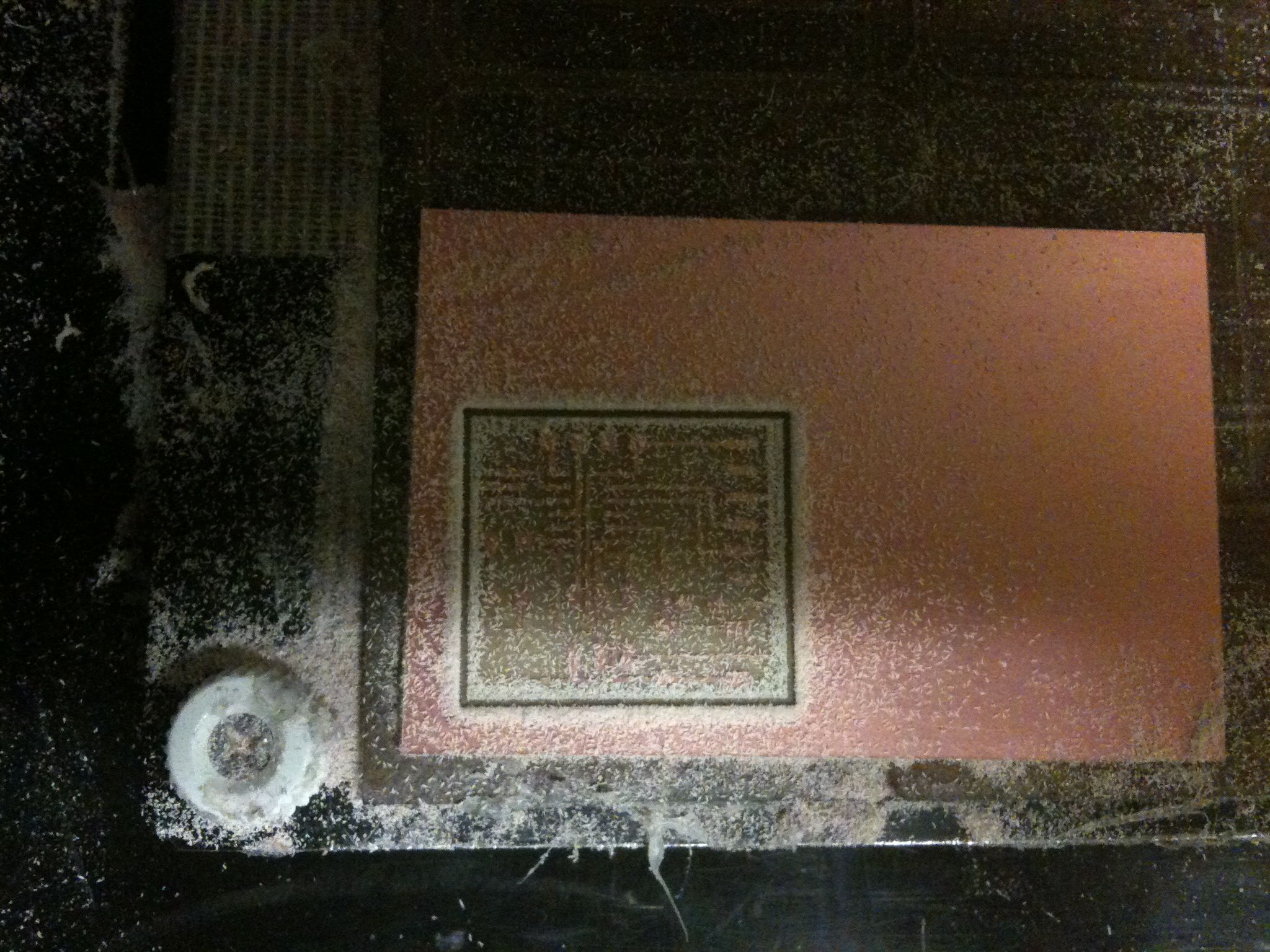
Using 3rd board as template for 4th board, with come caveats. Notice the sweet-ass 3d printed parts tray (which I did not make)
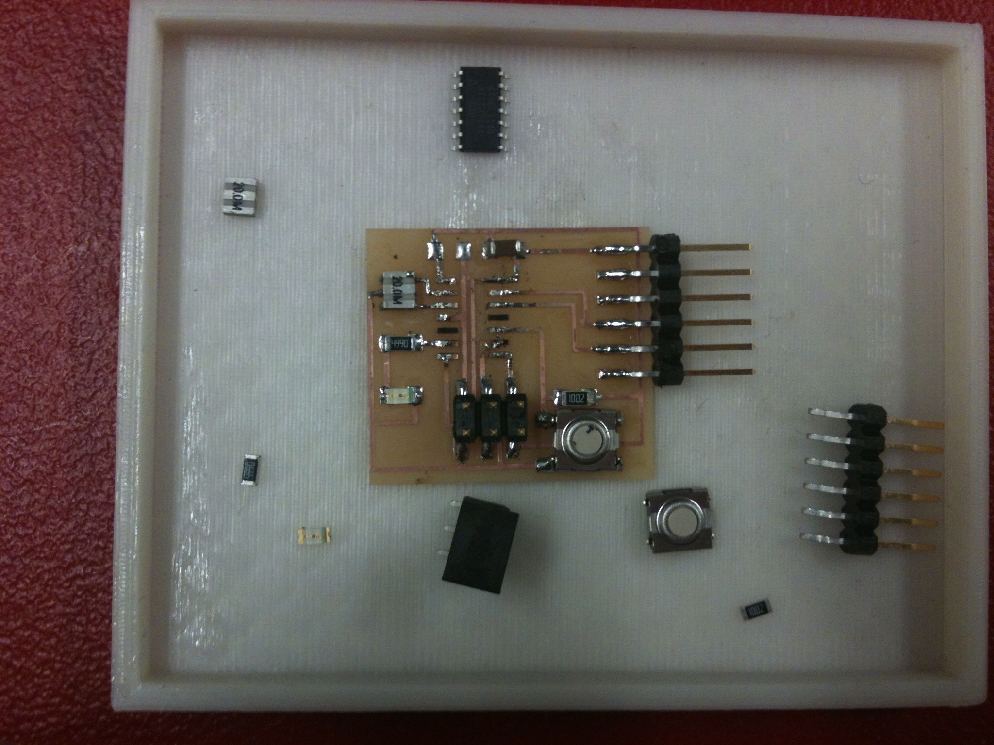
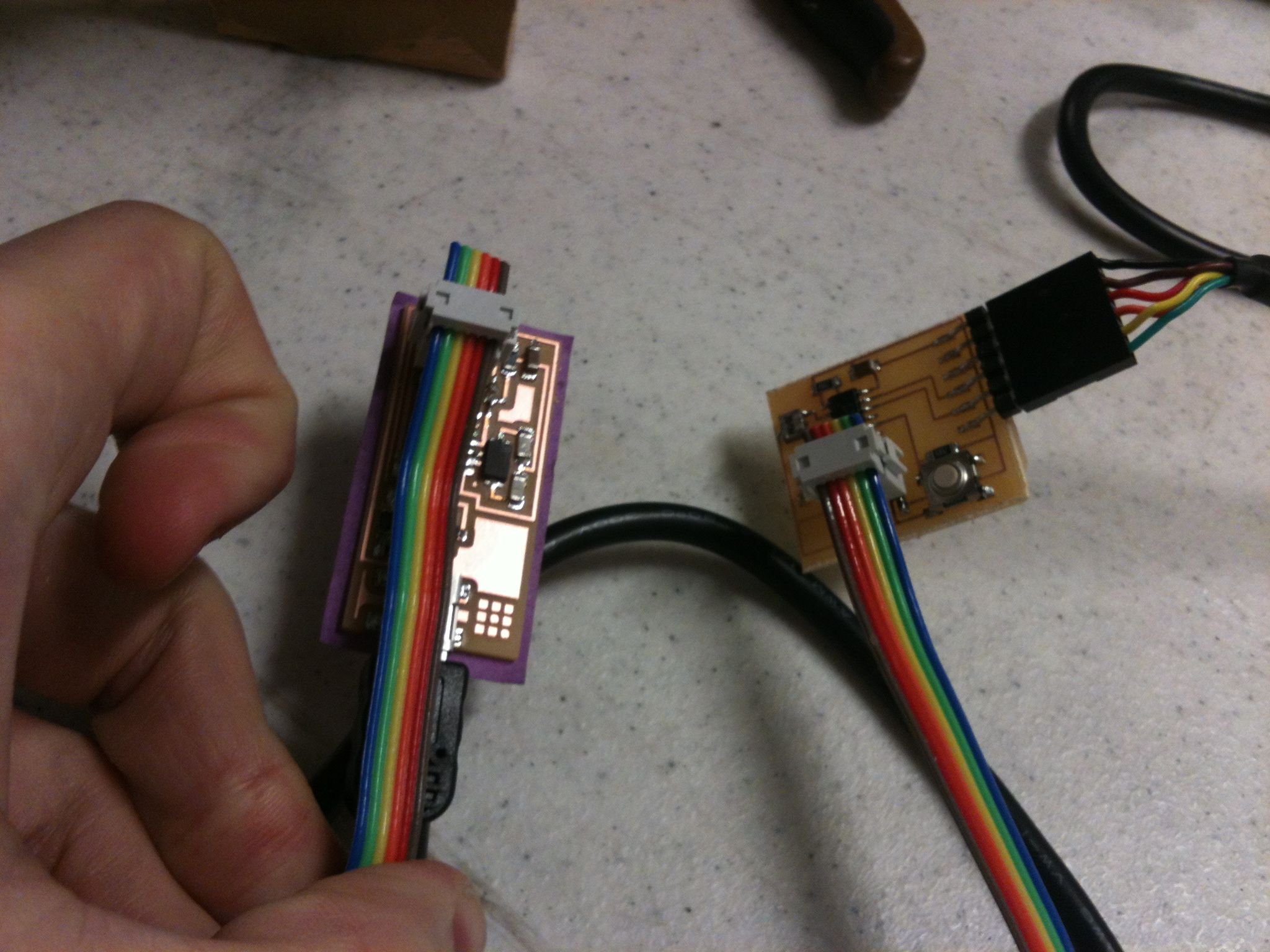
This is all hooked up correctly as near as I can tell
What I did all week
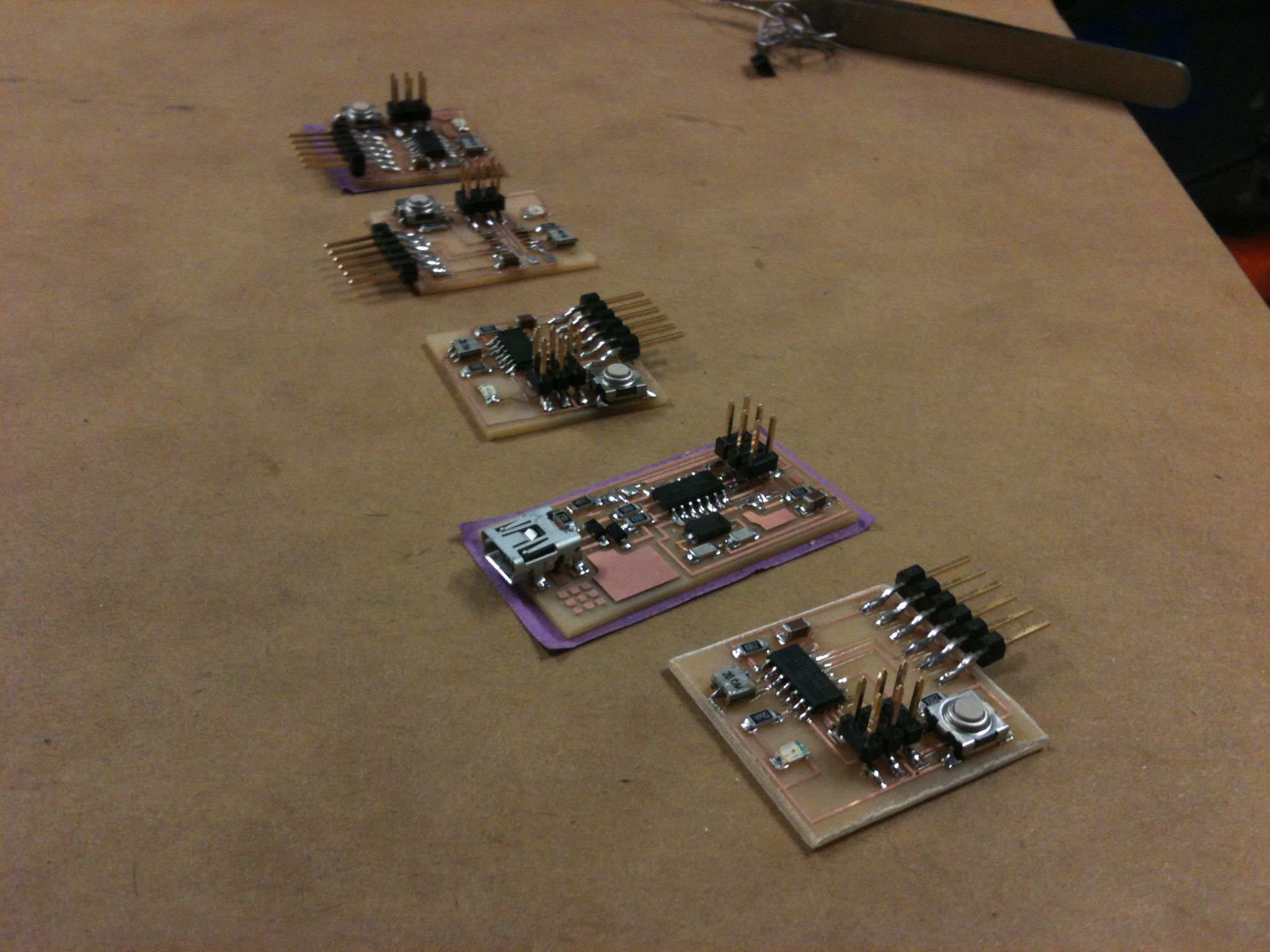
What I have to show for it.
Update - the problem this time was with the cable
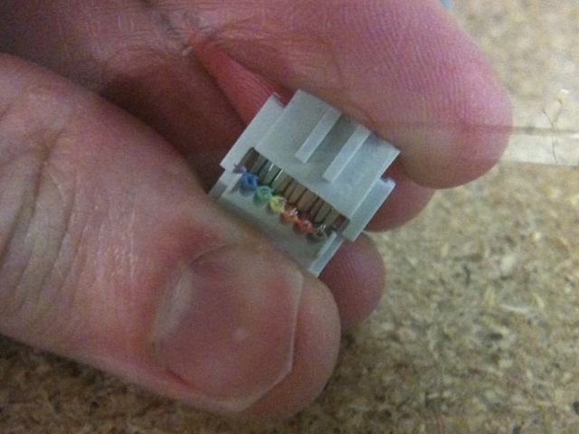
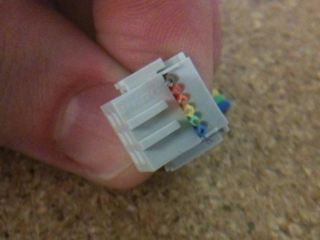
So the rainbow striped cable which connects the 6 pin on the FabISP to the 6 pins on the LED+Button is a build-it-yourself job. The way it works is you grab a piece of the rainbow striped cable, which actually consists of 8 or 9 different colored wires side by side, and the first thing you do is tear off all the wires except 6. (6 pins=>6 wires).
Then there are these little plastic plugs, which are the parts that actually interface with the 6 pins, and they have to be joined to the cables. The pluge have sets of 6 metal teeth set inside a pair of parallel sliding "jaws" which, when you close them on the wire tightly enough, pierce through the plastic sheathing and interface with the metal underneath, allowing current to flow through. This is all hooked up correctly as near as I can tell
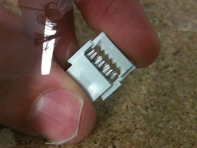
This is one of the plastic plugs with metal teeth.
Well, it turns out I didn't clamp down on those jaws hard enough and so they never penetrated the plastic sheathing. Which is why my 4th board didn't work. After applying some additional pressure to the connectors on my cable and giving it a second try, I was able to connect the board to my Mac and burn the fuses using the Arduino IDE.
This is what it looked like before
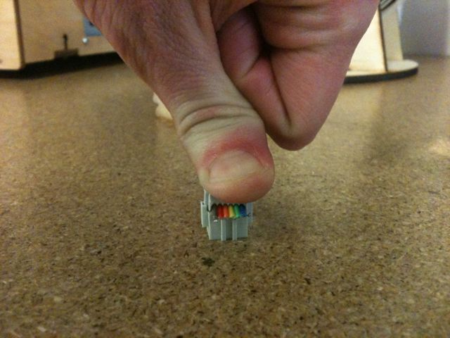
This is what I needed to do to make it work
This is what it looks like now.
21 March 2012
15:27
At this point I have successfully loaded the sample program (which turns the LED on and turns it off if I press the button) onto the LED+Button. Time to start mucking around now.
24 Mar 2012 11:30 am
I've been playing around with the Arduino code in a very rudimentary way. So far I've managed to get the LED+Button to start out with the light in the one state and then switch to the off state when the button is depressed. This is the starter code we were given as part of our assignment, and all we had to do to make it work was change a couple values indicating which pins to read and write from (the were incorrect by default).
From there, I tried reversing the HIGH and LOW commands (states? I don't know what to call these) so the code reads like this:
if (buttonState == LOW) {
// turn LED on:
digitalWrite(ledPin, HIGH);
for(int i=0; i<7; i++)
{
Which made it so that the light is OFF by default, and pressing the button turns it ON.
Ok, fairly straightforward stuff so far. While reading through the Arduino Notebook, I came across an example code for an LED, which causes it to pulse at varying levels of brightness. I cut and pasted a portion of this code into my own LED+Button code, so that the LED would pulse when the button is pressed:
// constants won't change. They're used here to
// set pin numbers:
const int buttonPin = 3; // the number of the pushbutton pin
const int ledPin = 7; // the number of the LED pin
byte flicker[] = {180, 30, 255, 200, 10, 90, 150, 60}; // array of 8 different values
// variables will change:
int buttonState = 0; // variable for reading the pushbutton status
void setup() {
// initialize the LED pin as an output:
pinMode(ledPin, OUTPUT);
// initialize the pushbutton pin as an input:
pinMode(buttonPin, INPUT);
}
void loop(){
// read the state of the pushbutton value:
buttonState = digitalRead(buttonPin);
// check if the pushbutton is pressed.
// if it is, the buttonState is HIGH:
if (buttonState == LOW) {
// turn LED on:
digitalWrite(ledPin, HIGH);
for(int i=0; i<7; i++)// loop equals number of values in array
{
analogWrite(ledPin, flicker[i]);//Write index value
delay(200);//pause 200 milliseconds
}
}
else {
// turn LED off:
digitalWrite(ledPin, LOW);
}
}
If the formatting's all screwed up here, oh Well. I'm typing this website out one line at a time by hand and it's not exactly conductive to maintaining attractive formatting or correct spelling for that matter.
Anyway, this isn't what the code looked like the first time I tried to cut and paste it over. The original code in the Arduino Notebook had some extra stuff that I had to delete, and it made references to different pin numbers, and of course it wasn't set to be triggered by a button, so I had to fix all of that stuff to make it fit with my code. I'm going to say that counts as programming my board and I'm officially done with this assignment.
Just for fun, though, I'm going to screw around with the array values (that's the string of integers separated by commas which are fed into the LED blinking sequence), and see if I can't get the button to do something more interesting.
24 Mar 13:00
I've adjusted the integers on the array and played with the timing to produce an LED which ramps up in brightness according to the fibbonacci sequence, which results in a very "organic" feeling to the light: