Machine Design
Wed (update)
Disseny
mecànic (actualització)
assignment
automate your machine document the group project and your individual contribution
FabLab LATHE 1.0 / The process
Drawing the cad plans
After a failed attempt trying to model the machine with solid works
we decided to use a 2D cad program to design the machine and rather than
star from zero with all the machine we started to take references from
other machines. We decided to use the same material and the same joint
strategies from the MTM SnapMachine.
http://mtm.cba.mit.edu/machines/mtm_snap-lock/
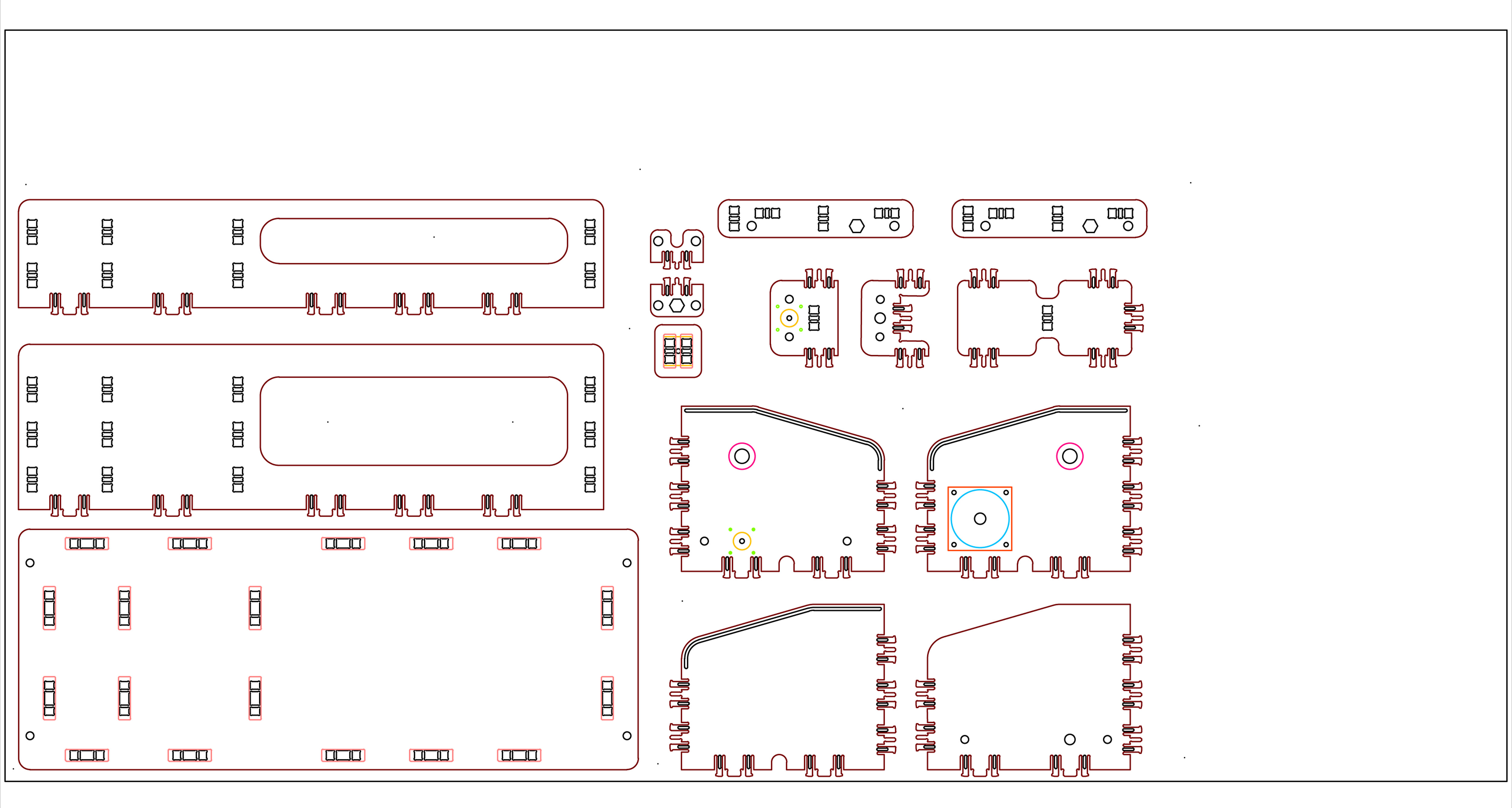
I downloaded the cad files (dxf) and I started designing the lathe machine
using the same strategies.
From 2D to 3D
After we had all the parts designed in cad we decided to model it in 3D
using Rhino (If you want to see images you can check in Santiago Fuentemilla
blog). The good thing in doing that is that you can check if there is
some mistake and some collision with the different parts of the machine.
We found some errors, so we had to redesign some parts.
Milling the parts
Once we had all the parts designed we done all the milling strategies
with RhinoCam. We done a sample for the joints to check that the system
was working well. We used the Precix milling machine. To mill the parts
we used a 3mm. tool and we designed an strategy milling the material in
3 phases (13 mm in total > 4,5 /4,5/4). The milling speed was 8 and 5800
revolutions per min. First of all we posted the holes to fix the board
in the sacrificial bed.
Final Version Rhino file / FABLATHE 1.0
Fablathe_1_0.rar
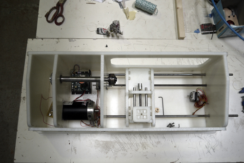
Assembling the parts
Here is where we find more errors in the design. We realized that we milled
some parts in the opposite side so we had to do a mirror of some parts.
We found some difficulties assembling the parts with more than three joints.
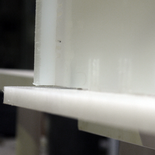
And also we had problems with some engravings that don't have any tolerances.
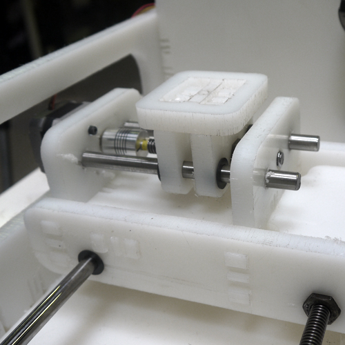
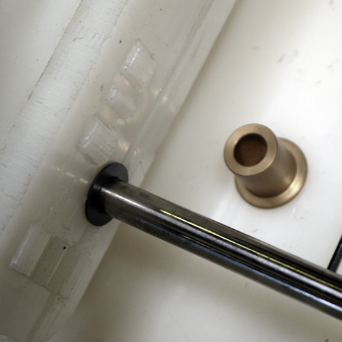
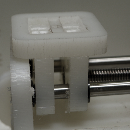
The most problematic part was the friction of the platforms with the rails.
We used a auto lubricated plastic bearings and maybe because the torsion
of the shafts the platforms doesn't slip correctly. We have to check if
the plastic bearings and the diameter of the shafts are correct.
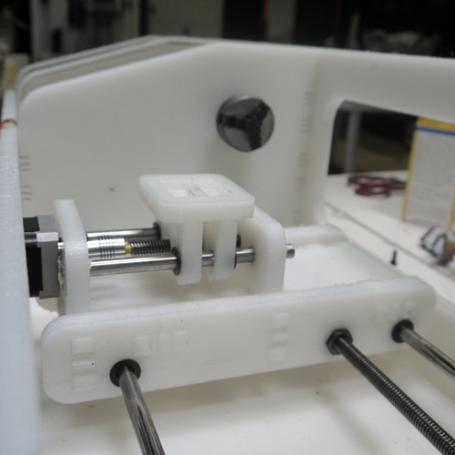
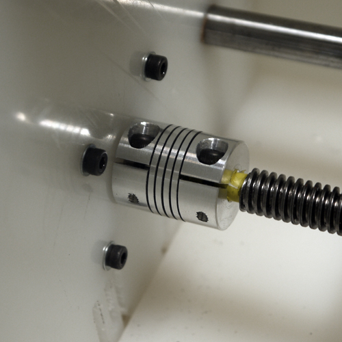
Another problem was the elastic connections we used between the servos
and the screwed shaft. Because the elasticity the platform accumulate
tension and the movement is not smooth.
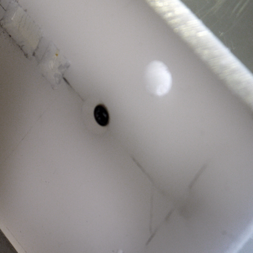
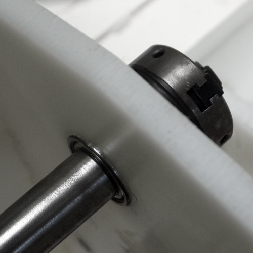
The engraving for the bearings of the main axis needs to be deeper because
it blends the intermediate walls.
Movie how the connections does not work properly
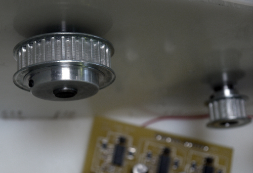
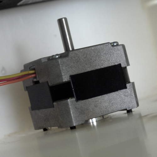
And finally we have to check the distance between the main axis and the motor. The size of the belt that connects the DC motor with the main axis it's going to determine this distance.