Machine Settings:
Photos:
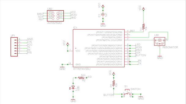
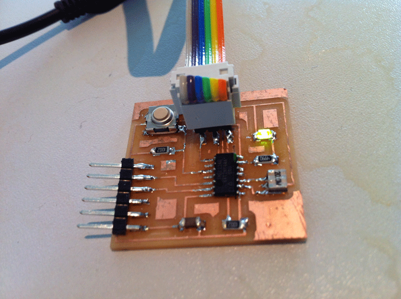
Weekly Assignment: Add LED and Button to Hello Serial Board
Narrative:
Designing the hello-serial board from scratch was
a good way to
learn how to use Eagle. The biggest problem
encountered was finding the
correct parts from the extensive libraries.
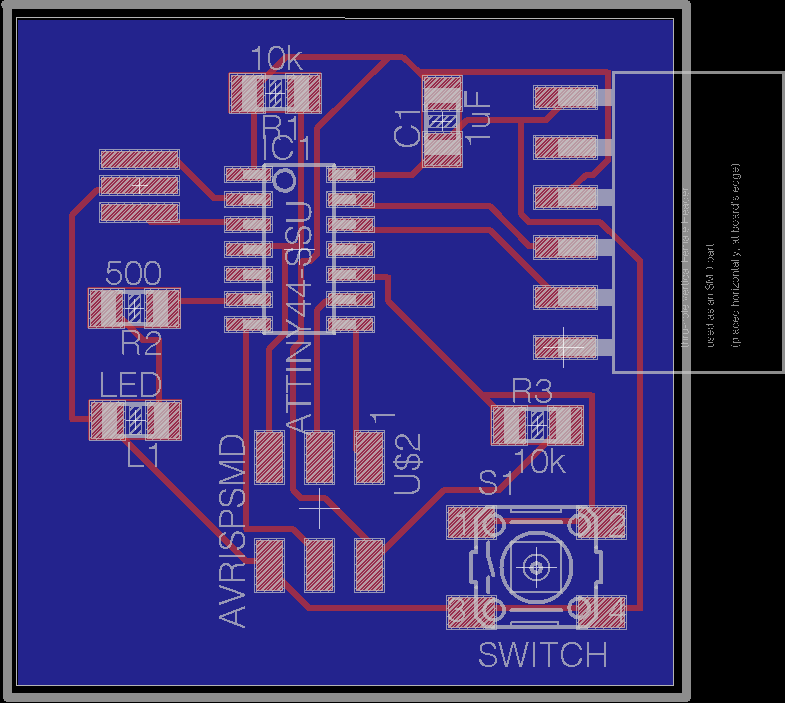
use nets - these can be linked to bus (eg VCC/GND
etc) - this make connecting and routing more simple.
check with desgn rules and electrical rules / change
routing from 8 to 16.
place components so traces can be sited - (use
ratsnest/auto) - save before auto since cannot undo.
export png files for traces/cutout/ schematic @500dpi
Use roland Modela to fabricate the board - see week5
- and stuff the board.
Materials:
Machine Settings:
Photos:
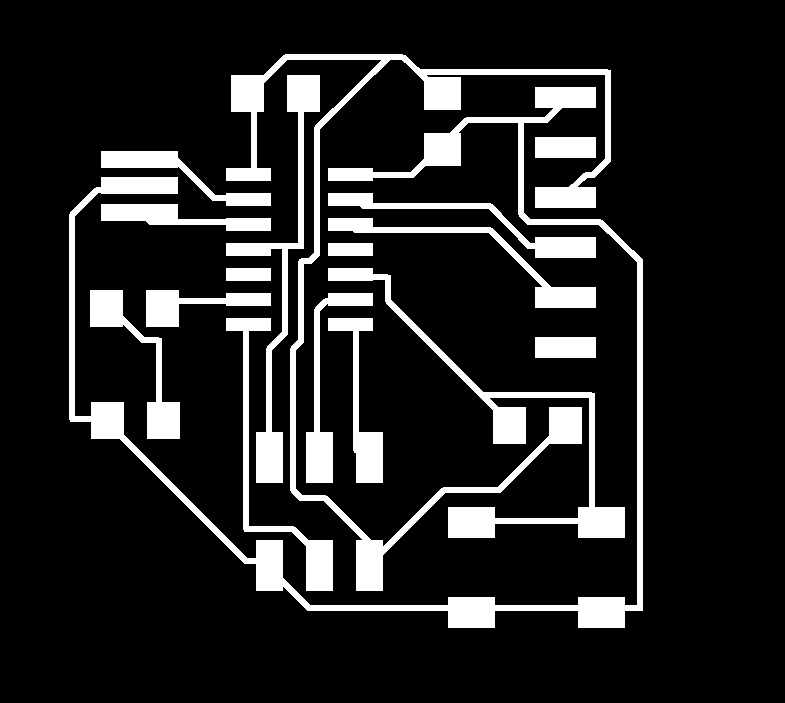
The files were used to mill the board - which was soldered up with the
components:
Comments:
Software: Eagle
Hardware: Roland Modela
Files:
Drawings:
External Links: