FabLab Academy 2012
Manchester Lab
David Forgham-Bailey
This week's task was to automate our machine - the FabScan3D_mod.
The electronics design has yet to be finalised. The aim is to produce
electronics which can be easily replicated by any FabLab.
Currently we are designing a system which utilises components from the
Fab inventory.
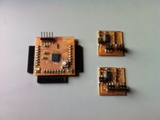
We aim to use the A4985 Stepper Driver Chip (620-1344-1-ND) - and the
USB to Serial chip (768-1007-1-ND) - with the control chip ATTiny 44 -
or the ATMega 328 (both in the inventory).
In the meantime I manufactured the Fabkit i/o
(aka Fabduino) and the hello.stepper
boards to create a development rig to test out software routines for
control of the two stepper motors and the Laser.
Programming the Fabkit proved difficult - the chip used was the Mega328
but Arduino only recognises the Mega328P chip which is fitted to the
commercial Arduino boards.
At one stage I managed to get the bootloader to complete - (by editing
avrdude.cfg), and the led on the Fabkit flashed ... however when the
FTDI cable was attached the board did not function...
I decided to try to reload the bootloader but this time it failed to
complete...(bad decision)..
Upon further investigation I found that the FTDI connectors did not
match the FTDI cable - Rx/TX wrong way round on the board... More
work required to bootload the board
correctly, and resolve the FTDI issue...
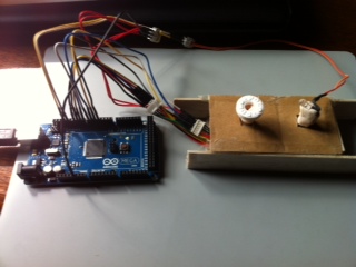
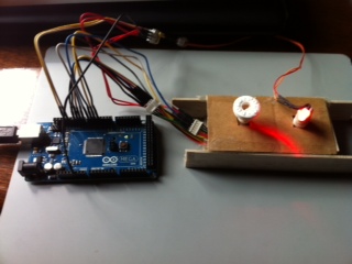
I decided to use a commercial Arduino Mega 2560 - with two stepper
motors from the Fab inventory (PF35T-48L4) - connected to pins 8-11 and
4-7, and a diode in place of the Laser - connected to pin13. Using the
Arduino programme I made up a routine to sequence the motors and the
led - stepper 1 moves one step - the laser turns on - the second
stepper moves through 1/4 rev and returns - then the first stepper
moves again to repeat until one full revolution is achieved... (these
steppers can be driven directly from the Arduino and have 48 steps per
rev - the motors we will use in the final machine will need a 12v
supply and have 200 steps per rev - so the routine will need to be
modified accordingly.
 video
video
Once we have designed and manufactured the final electronics boards,
this routine will be created in 'c' or Python.