FabLab Academy 2012
Manchester Lab
David Forgham-Bailey
This week's assignment was to add an output device to a microcontroller
board and program it to do something.
We were given a number of example boards with a variety of output
devices - so I decided to make as many example boards in the time
available. This would give me a feel for which devices could be
incorporated into my final project. I was especially interested in the
servo board since this could control two servos. My ventriloquist dummy
will have moving eyes and mouth - so the servo could be the solution
for controlling these movements.
The boards were milled using the Modela - in the usual way, then
stuffed and soldered. I decided to solder the boards with them lying
them flat on the workbench. This was much easier and quicker than
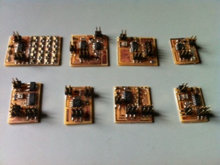
holding the board in a clamp. I made 8 boards in total:
This Photo shows:
Array/H-Bridge/LCD/RGB
Servo/Speaker/Stepper/Video

All these boards were programmed on the first attempt. A major step
forward in board production.
However not all the boards worked first time.
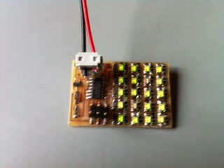
The Array Board worked once a battery was connected - but two leds do
not illuminate - further investigation needed:

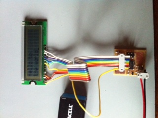
The LCD worked once the connections were made and the battery connected
- further work required to reprogram and change the displayed text:

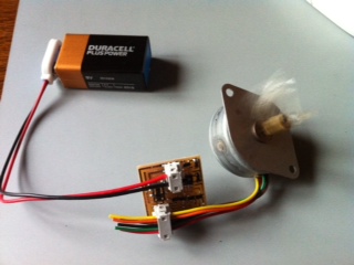
The Stepper Board was programmed for half and for full, and worked each
time:

The other boards have yet to be made to perform correctly. I suspect
that
the video board program will need rewriting to be able to work with a
PAL system. The Speaker Board has been programme with the supplied
routine, and also reprogrammed with the Simpsons theme, but as yet it
has
not made a sound - further investigation needed. The RGB board can be
programmed but will not light - further investigation. The H-Bridge has
not yet been tested with a motor.
The servo board can receive programming, but has yet to make the two
HTX900 servos move. This needs to be resolved.