WEEK_19_fab_academy_project_development_may_23.

1 / Comments about my Final (Art) Project 1 with FABDUINO :
Despite a lot of tries, my final project is not "working well" with the FABDUINO. There is no tutorials on the internet for combining a FABDUINO with a GLCD KS0108. The display shows the sketches but there are blank spaces on the display and you can't really see what's going on.
Since I admited I am not goog enough to make it work (for now!), I started to think that if I was the first to try my responsability was to document the process properly to provide some help to futur users. Maybe someone will just have a look at the sketch one day and say "I can solve that" (Actually, this is maybe you...or maybe not...).
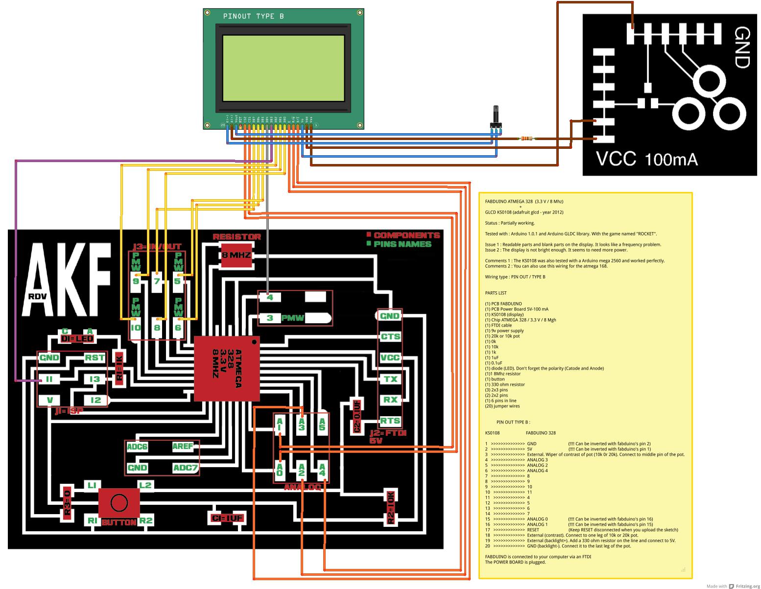
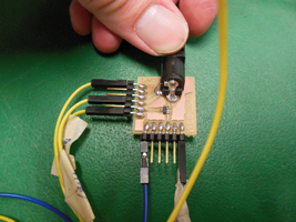
I am glad I remembered of Fritzing to make a good, as complete as possible, sketch of my project. My visual of this project is made of Anna's full pins FABDUINO and Power board. I designed this visual like I'd like a tutorial to be, and as simple as possible for a novice maker. It surely can be better, simpler, but I thing it's pretty good because you have almost everything you need on the same page. You don't lose your time searching for pages on your computer.
I have added each pin's number in green, components in red, a list of parts and the list of the PIN OUT TYPE B for the Atmega 328 (3.3V - 8Mhz), as well as the project's status, issues, and short comments.
1 / 2 / Preliminary tests with ARDUINO MEGA 2560 :
To make sure my issues were not coming from the devices (display, pot), I made preliminary tests with a commercial ARDUINO. And it's working well. The wiring examples I used also comes from the ARDUINO tutorial page for the KS0108. There are 4 options depending on wich board you use (PIN OUT A, B, C, D). I am using PIN OUT B. I also tried PIN OUT A (no success).
I have a MEGA 2560, and It would be easer to use an Arduinno UNO instead, because it's older, cheaper, and lots of people are using it and already have their works documented ont he web. The more inportant thing is that the UNO and the FABDUINO I made have the same chip. Wich should make everything easy.
If there is a lesson I learnt during this final project conception, this is that I should have choosen a simpler display which was used by more experimented users and well documented. This is frustrating to not complete the goal with FABDUINO, but in the other hand, someone has to try and share his experience. This is how it works.
The issues I have been through to get my display working lead me to the next observation : Most tutorials I found were very incomplete and uncertain. There is always something missing. We need well made protocols, and I'll be keeping that in mind because the quality of a tutorial is crucial for spreading technical infos. This is a delicate task of calibration and didactic.
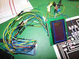
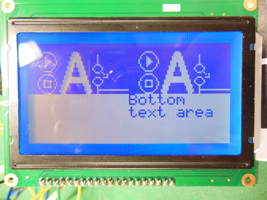
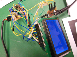
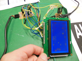
1 / 3 / Real tests with FABDUINO :
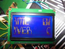
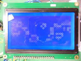
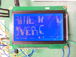
As you can see on the pictures the display is showing blank parts and cuts. It is also brighter because I have connected more pins to the power board. It has more juice and look more punchy though. But I not sure if it's alright. It could prematurly burn the backlight.
When I upload a new sketch and reset the board, both sketches melt together on the display and it's bugging. This is what makes me think it's a frequency or a memory issue.
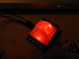
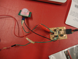
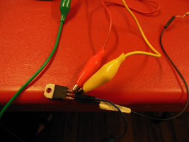
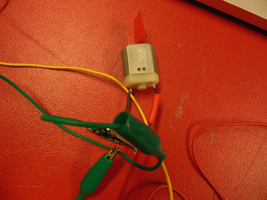
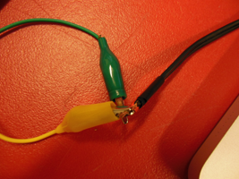
1 / 4 / PIR sensor tests :
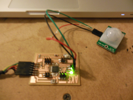
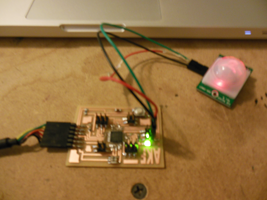
At the very begining of this project, the main idea was to oblige the display to start playing something when someone was approaching the case I am using for this artwork. This is not a problem at all to make a PIR sensor work with a FABDUINO. The PIR sensor only needs 3 pins. The BAUD to read the data is as usual : 9600. Something was finally working ! Click on the last picture on the right.
2 / Final (Art) Project 2 :
Like I said, I had to abandon my first final project. As I had to figure out this second final project after the fab academy program was finished, as I will be mouving back to France in a few days, I have limited my final project to the completion of the electronic part. This final project 2 works very well. The PIR sensor detects motion and the DC motor starts turning. This is that simple. Just watch the video below.

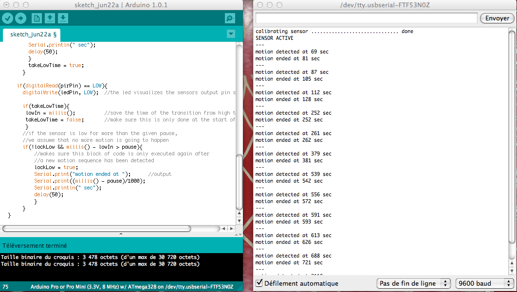
2 / 1 / Final (Art) Project 2. Arduino Code :
// Parallax PIR sensor's output

//VARS
//the time we give the sensor to calibrate (10-60 secs according to the datasheet)
int calibrationTime = 30;

//the time when the sensor outputs a low impulse
long unsigned int lowIn;

//the amount of milliseconds the sensor has to be low
//before we assume all motion has stopped
long unsigned int pause = 5000;

boolean lockLow = true;
boolean takeLowTime;

int pirPin = 3;    //the digital pin connected to the PIR sensor's output
int ledPin = 13;

//SETUP
void setup(){
  Serial.begin(9600);
  pinMode(pirPin, INPUT);
  pinMode(ledPin, OUTPUT);
  digitalWrite(pirPin, LOW);

  //give the sensor some time to calibrate
  Serial.print("calibrating sensor ");
    for(int i = 0; i < calibrationTime; i++){
      Serial.print(".");
      delay(1000);
      }
    Serial.println(" done");
    Serial.println("SENSOR ACTIVE");
    delay(50);
  }

////////////////////////////
//LOOP
void loop(){

     if(digitalRead(pirPin) == HIGH){
       digitalWrite(ledPin, HIGH);   //the led visualizes the sensors output pin state
       if(lockLow){
         //makes sure we wait for a transition to LOW before any further output is made:
         lockLow = false;
         Serial.println("---");
         Serial.print("motion detected at ");
         Serial.print(millis()/1000);
         Serial.println(" sec");
         delay(50);
         }
         takeLowTime = true;
       }

     if(digitalRead(pirPin) == LOW){
       digitalWrite(ledPin, LOW);  //the led visualizes the sensors output pin state

       if(takeLowTime){
        lowIn = millis();          //save the time of the transition from high to LOW
        takeLowTime = false;       //make sure this is only done at the start of a LOW phase
        }
       //if the sensor is low for more than the given pause,
       //we assume that no more motion is going to happen
       if(!lockLow && millis() - lowIn > pause){
           //makes sure this block of code is only executed again after
           //a new motion sequence has been detected
           lockLow = true;
           Serial.print("motion ended at ");      //output
           Serial.print((millis() - pause)/1000);
           Serial.println(" sec");
           delay(50);
           }
       }
  }
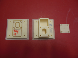
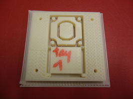
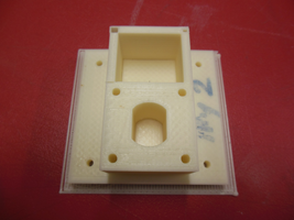
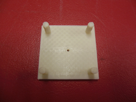
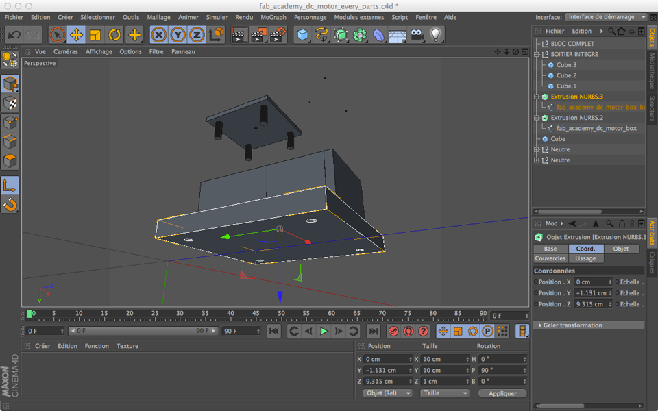
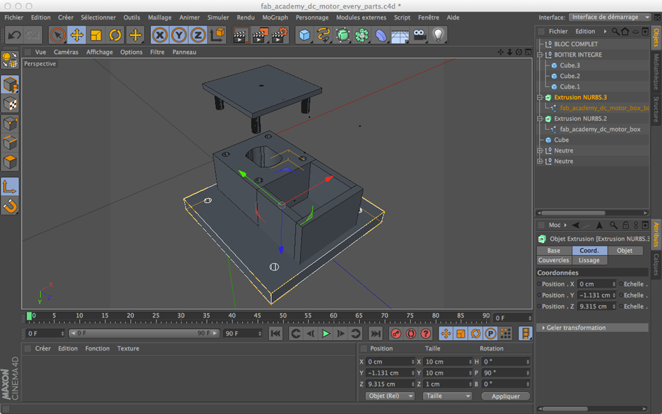
2 / 2 / Final (Art) Project 2. Extra parts. The BOX/MURAL SUPPORT :
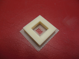
Here are the parts I have also been working on before leaving Providence. There is a 3D printed box I conceived for the DC motor on C4D. The Makerbot, once again, didn't work well and I had to stop the try 1 because the base of the object was bending. By chance, the object on try 2 was properly leveled on the upper side of the volume despite the bending. It took 7h48 to print it with a 25 % fill. The scale I used was +9.6. I assume I should have scaled it at 10 because the hole is just a little smaller than the dc motor I have (3/4 mm). I would need to adjust it and print it again. The 3D files below were corrected because the volumes were kind of inserted one into another and this produced some unwanted shapes on the prints.

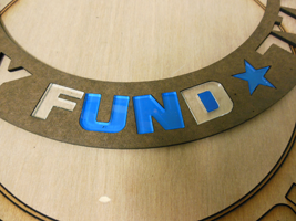
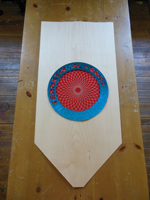
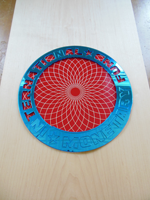
2 / 3 / Final (Art) Project 2. Extra parts. The wheel :
Here is a wheel I laser cut from a mirrored acrylic sheet and also from a masonite sheet and from a common acrylic sheet. I am not fully satisfied of the results. I made the design on Illustrator CS5. I also made a series of tests to raster a rosace on the surface of the acrylic seet, but didn't really like it either. This will is supposed to be attached to the wall directly, while a smaller wheel in the middle would be attached to the dc motor and would start turning when motion is detected by the PIR sensor.
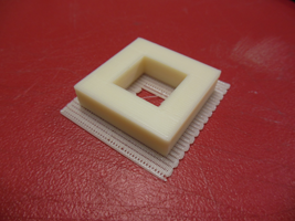
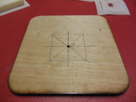
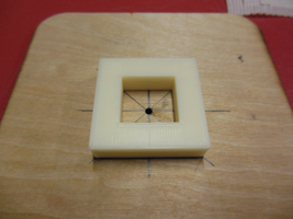
2 / 4 / Final (Art) Project 2. Extra parts. To stick the motor and the wheel together :
Here is a block I 3D printed on the Thing'O'Matic. I made it with Illustrator CS5 and C4D. The hole inside will the motor's wheeling pin. The idea it to temporarly place the motor on a wood platform, to center the block, and then to put some liquid plastic into the hole so that the motor's pin cannot separate from the wheel.