
As mentioned in the assigment "Applications and Implications", the parts to be made for the Pick and Place (PnP) machine are:
The cabinet and tool support for the pick and place tool
The dispenser
The pick and place tool
The electronics controller
The software
The mechanical specifications for the cabinet are:
X(mm) |
Y(mm) |
Z(mm) |
|
|---|---|---|---|
Cabinet |
375 | 175 | 250 |
Base |
440 | 335 | ------ |
Bed |
305 | 120 | 70 |
Other important requirements are:
Low cost materials
Easy assembly and maintenance
Multipurpose (milling, solder dispenser, heating gun)
With this specifications, Alejandro designed the cabinet in Rhino, as you can see in the next picture.
For the cabinet implementation we are going to make first a prototype in MDF and after the final design, test and evaluation we will make the machine in HDPE.
The cabinet components were computer controlled machined in the shopbot, then we proceeded with assembly, as the figure shows.
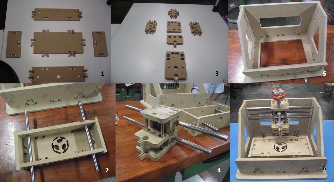
The figures show: 1 and 2, the bed; 3 and 4, the tool support; 5 and 6, the cabinet assembled.
One of the important tools raised for this project is the dispenser. The components are placed on the dispenser and will be taken from there to be transferred to the card. The reason for using a dispenser is because it faciltates the transport of the components to the board. There will be a dispenser for each card model.
I manufactured the components' dispenser in assignments 5 and 7, I made two models, one casted with Hidro-Stone and the other printed in ABS.
Once completed the construction of this prototype, we will make the change to take the components directly from it original packaging.
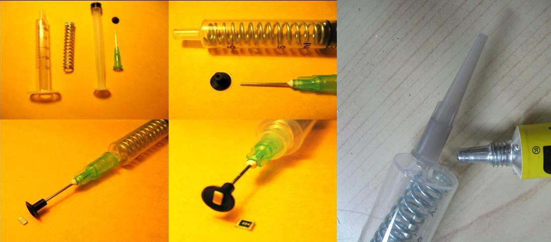
The pick and place tool was manufactured with a hypodermic syringe, a wire spring and a vacuum pick up tip. We had problems with suction of components, we fixed this applying a silicone sealant between the needle and the suction tip, and a lubricant in the plunger of the syringe. I also tried with other types of syringe like the showed in the figure; it has a plastic needle, but it hasn't enough suction because the diameter of the plastic tip was big respect the diameter of the rubber suction tip used with the metal needle. I've seen this plastic needle been used in systems with a vacuum pump for improving suction of surface mount devices.
The electronic controller design was based in the Allegro A3982 Stepper motor controller with translator, this means that simply inputting one pulse on the STEP input drives the motor one step. There are no phase sequence tables, high frequency control lines, or complex interfaces to program as with other circuits, this is the same chip used by the MTM Snap lock machine. Some of the advantages here:
There is a Data sheet from Allegro A3982, but there aren't application notes, so I had to review the web about the design, fortunately there are many people using it and reports there experience. Some of the control pins of the chip are:
Enable: Sets the state of the chip, enabled or disabled. When pulled low, the device is enabled. With pulled logic high, the device turns off all outputs and the chip is disabled. In this design there is a pull-up resistor connected so as to set the default state to disabled.
Reset: Resets the chip to it's default. Pulled low to perform a reset. A pullup resistor is added to stop the driver floating into reset mode.
MS1: Microstepping select - only 2 levels of microstepping are avialable on this particular chip, none and 1/2 stepping. A pulldown resistor is added to make it default to no microstepping. The pin is pulled high to enable 1/2 stepping.
Direction: Sets the rotation direction. When pulled low rotation is clockwise. When high, anticlockwise.
Step: When the pin state transitions from low to high a step is performed. No action is taken on a high-to-low transition. A pulldown resistor is connected to this pin.
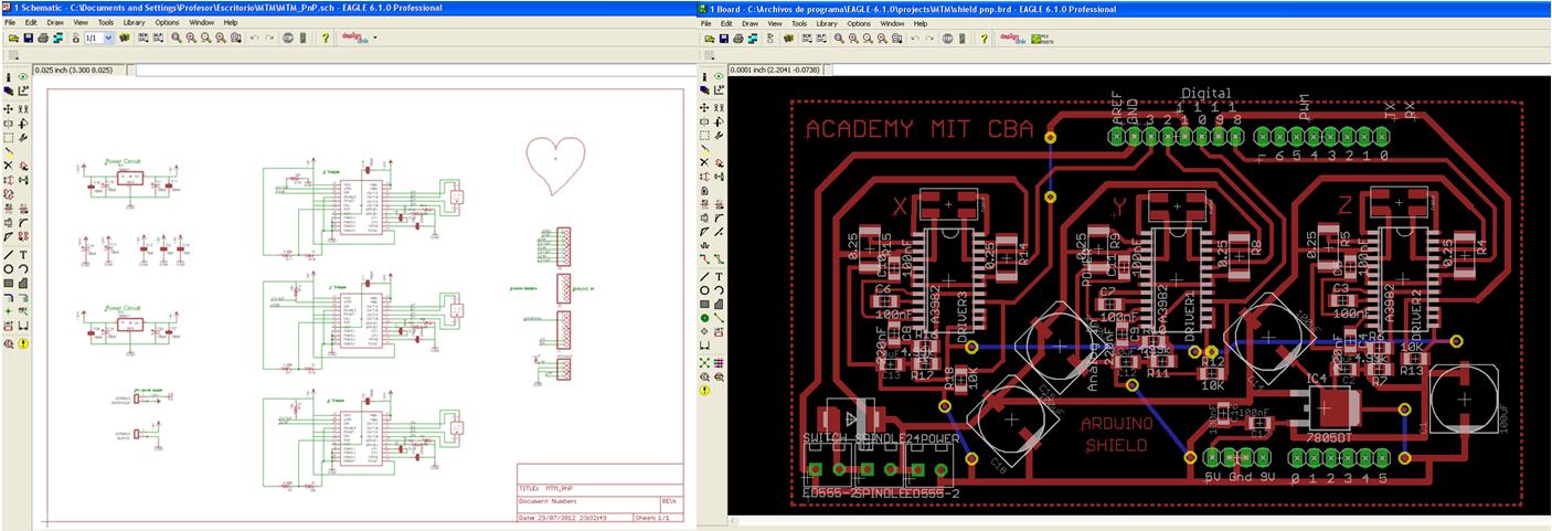
First I made one board using the MTM snap lock schematic, previous some modification showed in the last figure. Unfortunately our board burned, because the mechanisim was not smooth enough and drained to much current from the board. Fixed the mechanisim, I made other board, but that only worked with to steppers (for x-y axis), the other (z for z axis) ran intermittently, so I have read about a lack capacitance, so I put more capacitance to the circuit , it works but finally I had to change the chip. The figure below shows the boards
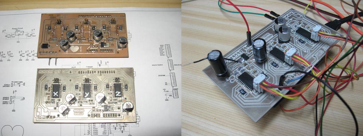
The figure shows the boards with the controller. At left the upper board was the first, as you can see it has no chips (all burned), the board at the right has more capacitance
I'll have to make some changes to the circuit design, placing another regulator for the servo that moves the plunger of the PnP tool, also I'll place a series zener diode or +12V voltage regulator between the 24V DC input and the +5V voltage regulator, because the voltage difference in the 5V regulator is too high (19V) and is the cause that the regulator heats in excess. The added capacitance to the 5V regulator helped in reduce the heat dissipation because improved the ripple.
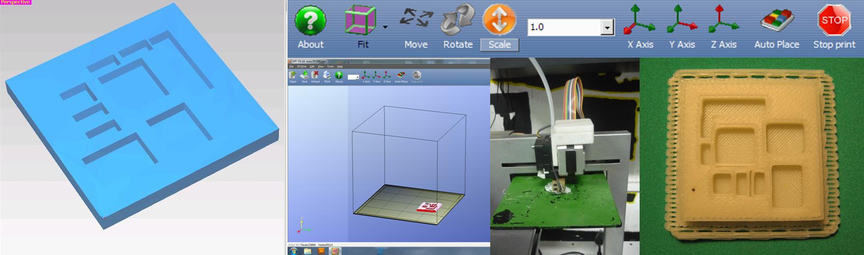
The software took me a lot of work. First you have to know well what you want from the machine, in this case we just need that the machine picks a component from the dispenser and place it on the board. Of course that there are intermediate steps like applying solder paste to the pads on the board, this is necessary because when you place the component the solder paste helps to keep the component in place, I don't have now solder paste, so I'm going to use two dispensers for the simulation and when I have the solder paste, I'll make a stencil (maybe with the Modela or the laser cutter) in 200um acetate for applying solder.
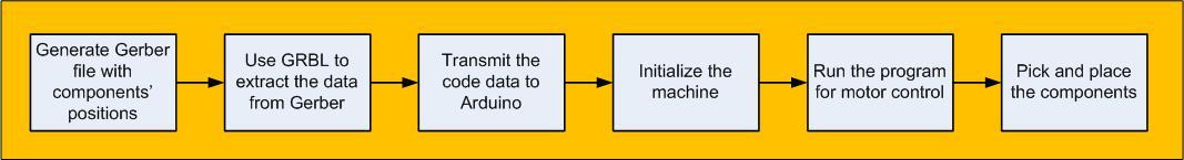
From this block diagram I define the software modules required. The program code will be done for running with Arduino.
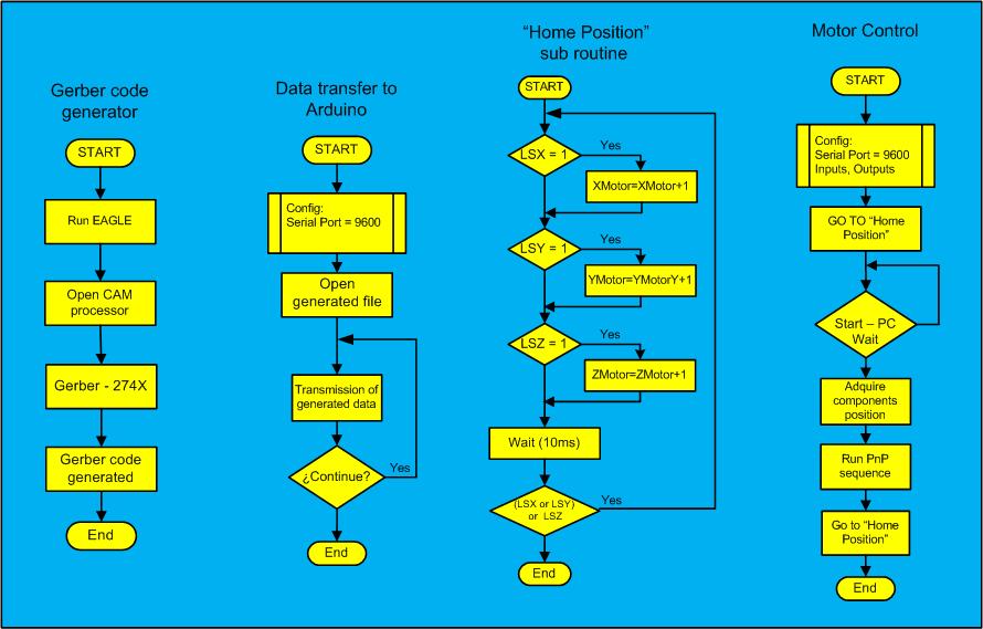
The following figure shows four flow diagrams corresponding to the functions of the PnP machine
Now I'm developing the programs, with Arduino is easy but I've no much time. In the next figure you can see some sketches to control the motors, that I used to test the machine.

Following you can see the code that has been developped. Program code
It seems to me that this is just the beginning.