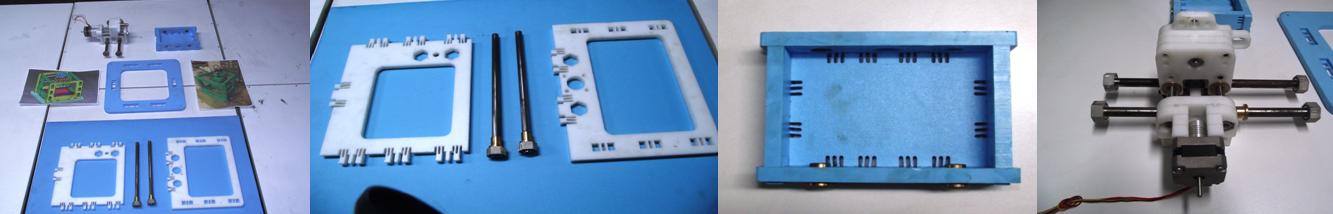
This week we were assigned to assembly a MTM Snap. We received the mechanical parts and the frame unassembled. Initially we just had a photo, so we got the bill of materials and the dxf files at MTM_snap_lock. We also had a set of unused mechanical parts (shafts, leadscrews, bearings, bushings, nuts, etc)
but we didn't know how many of them we were going to use, so with the bill of materials we could choose the parts.
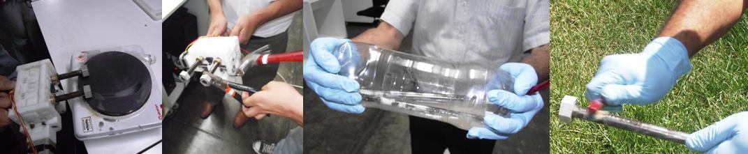
After the inventory, we unassembled the spindle frame, removing the shafts (heating them in a stove) because they were with rust so we cleaned them with a chemical biodegradable cleaner.
First we had to fit the sides and the bottom, this was not an easy task, we had to apply some force and use a rubber hammer also. The structure remains rigid. It took us more labour the installation of the leadscrew with the shafts and all its accessories.
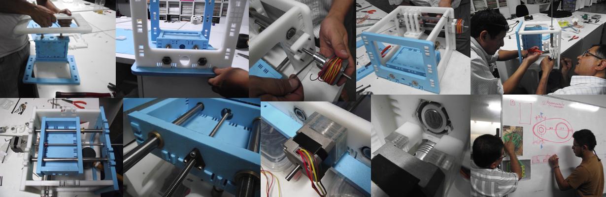
The most delicate task was to assemble the spindle, we were confused because the bill of materials specifies a timing belt and a pulley for coupling the dc motor shaft, but our machine uses a flexible shaft coupling system.
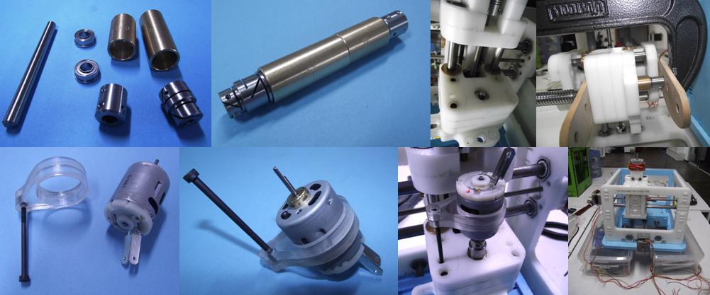
We test manually the x-y movement, rotating the leadscrews and we test also the Dc motor with a power supply, we apply low voltage to see the movement. The body of the DC motor was supported by a piece manufactured in acrylic.

Here I show some videos
I worked in this assignment with Alejandro. Diego also helped us with the design and manufacture in acrylic of some parts that were missing.
We also thank the students of Professor Jose Oliden, which gave us many ideas and helped with the assembly.