Make Press Fit Kit
The Assignment is to make a press fit kit To get an easy fit chamfers make this less of an effort.
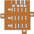
I was advised by my peer group to make a test piece , as we are in a shared learning environment was assisted by my colleagues , this piece had graduated tabs and slots a graphic representation is shown below. This allows the assessment of both friction and material strength. The material of choice was corrugated cardboard with thickness of 2.7mm.
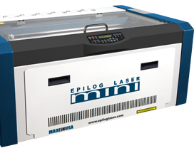
Designing Components The lazer cutter at the Manchester FabLab is a Epilog Mini 24,This machine has a Carbon Dioxide Lazer (CO2) with variable wattages from 30 to 60 watts in steps of 10 watts, The Bed is 600mm wide x 300 in height. More details may be found at:
http://www.epiloglaser.com/legend_mini24.htm
Cutting ComponentsThe card size was 600 x 300 mm by 2.7mm thickness.
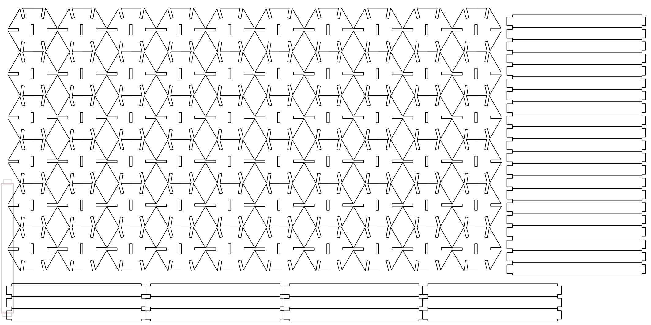
The components were a modern representation of the "Ball & Stick" models used in Science Labs to model molecule structure, My choice of shapes are a hexagon with a central 2.7mm by 10mm slot and 6 x 2.7mm slots 10mm in length one on each face. The Connector being a rectangle of 75mm x 14mm width with recesses of 2 mm cut from each corner.
The components were drawn in Inkscape as a SVG file with a 1mm line thickness. The component shapes were cloned and tiled to fill a piece of cardboard 600 x 300mm this was then copied en-block to a second file with a line width of 0.01mm which is the cutting width of the Epilog's Lazer this is then saved in PDF Format which then can be loaded to the Epilogs controlling computer where the cut is set up and sent to the machine in the same way as a document is printed.
This is a single component hexagon

A rectangular connector
These are shown as a sheet ready for cutting