The Round Tuit
3D Printing in ABS
Concept
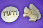
The concept of the "Round Tuit" is not new.
I with all my commitments do not have time just for FabLab Assignments! I wish I did.. However just to remind me that all that has to be done in running a very busy household , being a carer and having time to get as much benefit from the FabLab experience like needing to be at least 20 years younger and 40 free hours a week!!! . The thought of being able to do this a pipe dream.
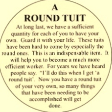
Rejoining the "Real" world with all its trials and tribulations , we often forget that tasks have to be prioritised so I have decided to take the concept of the "Round Tuit" and make a desk weight as part of my 3D printing assignment so when important tasks appear on my desk they can be placed underneath this so they wont be missed.
Preparation
The Manchester Lab has a 3d Printer model aDimension 1200es.Having had a short walkthrough the hardware & and a tutorial on the workflow of 3d printing project.
Salient points appertaining to this particular model of printer :
- The printer builds your part up in layers of 0.25mm
- To realise detail on parts such as words a 1mm resolution gives good results
- Allow 0.5mm gap for moving parts
- If making a complicated shape. Use the layer function to check tool paths in catalyst ® software.
Stage 1 Drawing in Google Sketchup ®
The first stage was dictated by the text of the assignment cost in price & time available , I viewed "small" as a maximum diameter of 50mm by 10mm thick.
The model needs a circular form; before entering the diameter GUI asks for the number of sides so I selected 360 sides (Google Sketchup ® will take a maximum of 1000 sides) The greater the number of sides the better the resolution.
The resultant circle centred on the point of origin of the meeting of all the axis is created with a diameter of 50mm and using the push/pull tool extruded 10mm.
The Text was created in a san-serif generic font 24pt which has a cross sectional thickness of 1mm; this is the minimum thickness the printer can extrude in a vertical plain without falling over.The Google Sketchup ® 3d text tool produced the "TUIT!" lettering this was then placed on the extruded base in the centre.
To ensure that the whole entity of the design was as one. all the nodes were selected with "ctrl a" keystroke then using the function "create part" the design became a solid object.
At this point the project was saved as a sketchup file and also exported using the Ruby script plugin to export as an .stl file ready for importation into netfabb ® software.
Below the output as viewed in Google Sketchup ® :

Stage 2 Repairing Meshing with Netfabb ® Software
Using the freeware version of Netfabb ® software the "TUIT" .stl file was imported , a quick check revealed many errors which would prevent the part from being acceptable to the 3d printer.
The Errors
The errors related mostly to incorrect orientation of the mesh triangles. These were resolved using the "Automatic" repair function in Netfabb Studio ®.
The resultant repair is shown Below:

Printing
The part (round tuit) was saved as a repair .stl file in Netfabb ® Studio , the printer has its own suite of applications Catalyst ®
"Catalyst software automatically imports STL files, orients the part, slices the file, generates support structures (if necessary), and creates a precise deposition path to build your ABS model. Multiple models can be packed within the build envelope to maximize efficiency. Catalyst provides queue management capabilities, build time, material status and system status information."
Further details on the aDimension range of printers is available at:
http://www.3dimensionprint.co.uk/printers/printing-main.shtml
Dimension 3D Printers run unattended and provide system and build status information via e-mail, pager, or the Internet.
Once the printer had warmed up (from cold took nearly an hour) , the printing environment has to be kept at a constant 70 degrees, the door locks and takes over leaving the user time to start another job.
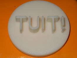
Below is the finished "Tuit" having taken just 27 minutes to print:
Squirrel Key Charm
3d Scanning with the Roland Modela
Concept
The 2nd part of the 3d Scanning & Printing assignment involves using a physical object which needs to be digitised and reproduced in a 3d form. My choice a wooden carved squirrel off my key chain. The original object is shown below:
Step 1 Scanning
The Modela MDX has two functions as a cnc milling machine & 3d scanner.
The Milling Head is removed and replaced with a scanning probe. The probe works by utilising the "Piezo Effect".
The Roland system is known as "Piezo Sensor (RAPS)®" technology,when scanning the probe touches a surface the software logs the position of the X,Y & Z axis when a voltage is detected. The points can be stored in a variety of the formats the most common being CSV (Comma Separated Value) as seen in spreadsheets.
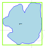
Preparation
The process of scanning on the Modela ® is not quick even a small object such as the squirrel which is 56mm x 50mm x 10mm thickness with 0.5mm resolution took just less than 2 hours to scan. The resultant plot is shown below:
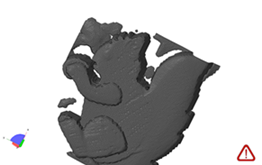
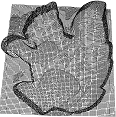
Step 2 Repairing in Netfabb ®
The .stl file is imported into Netfabb Studio ® and opened the mesh shows errors which as previously described are unacceptable due to orientation errors these are closed using the auto repair. This processing had to be carried out 4 times as each repair left errors. The item then needed post process repairing manually by opening the mesh file and manually deleting excessive triangles. This is both time and labour intensive taking a further hour.
Below is the resultant catalyst repaired scan as a repair.stl file:
Stage 3 Printing Using Catalyst ® Software
The repair file as shown above was opened in the the Catalyst ® software , The scan has several stages in this suite to be transformed to a file with fine enough definition for the printing head. The Orientation of the job is set , the density of the ABS plastic is selected from a range of values depending on the use of the part from solid (high density) sparse (medium density) & normal (low density) by selecting the appropriate part strength this not only saves time but cost of printing as the amount of ABS used varies quite significantly.
A further time saving factor is how the item is loaded onto the printing surface. The bed on which the ABS is deposited is 250mm x 250mm the heads are at rest in the top right of the enclosure so loading the job in the top right (the images of the jobs are aligned on screen on a grid) when "adding to pack" saves time as shown below:
Stage 4 Finished Item
In Conclusion
The Item took around 50 minutes to print , in this time the write up was started , overall the second phase of scanning the physical object took much longer than expected and the post processing was very labour intensive & time consuming and the printing of the object took almost twice as long.
Below the finished items are shown for comparison: